Táltos-oid ~ A Supernumerary Robotic Finger
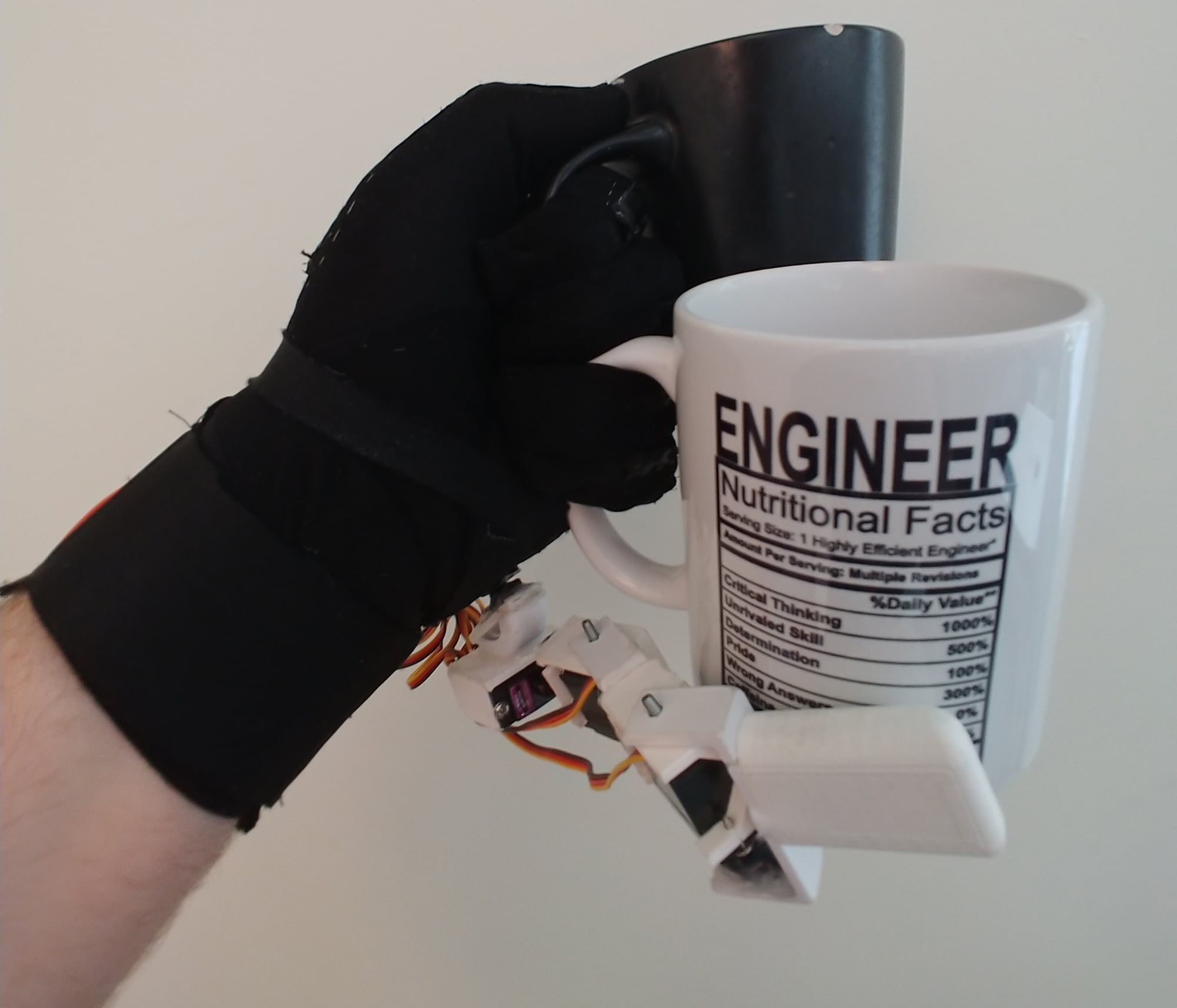
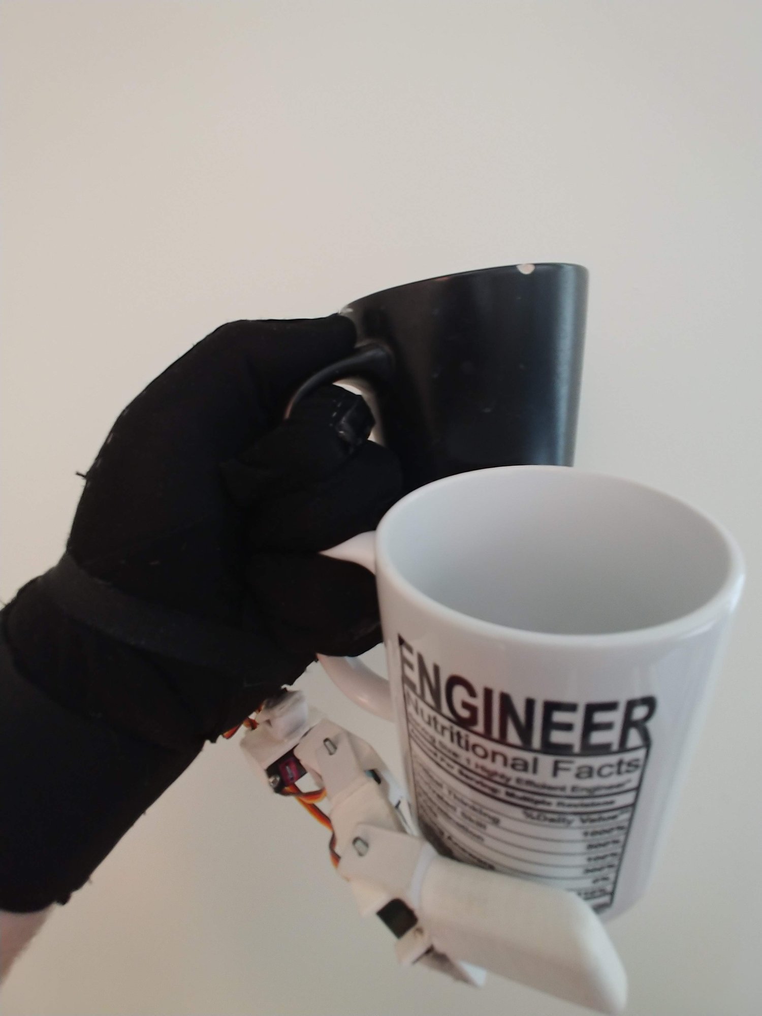
Táltos is the shaman of Hungarian mythology, and one of the traits that supposedly marked someone as a táltos was being born with a physical abnormality, like an extra finger. So a Táltos-oid is a shaman made with robotics. Or, less grandly, it’s a 3D printed thumb strapped to the side of my hand so I can hold two coffee mugs at once.
This is the build write-up for a course project from the spring of 2019, my first year of grad school at UW-Madison. The course was CS 518: Wearable Technology. The weekly build logs went on the course site, which has since gone offline; the Wayback Machine kept the weekly posts1 and the final write-up. The repo went up on GitHub that spring with “work in progress” at the top of the README, and that’s where it stayed. I picked it back up briefly in 2024, wrote some notes about how uncomfortable it was to wear, and put it down again. Time to at least document version one properly.
Why an Extra Finger
I have been fascinated with augmenting the human body with robotic limbs for a long time, nearly as long as I have known the words transhumanism and post-humanism. There is something captivating about the question “what would be different about me if I weren’t human?” A supernumerary robotic finger is about the smallest, cheapest way to poke at that question with actual hardware, noninvasively. It could also just be useful. An extra opposable digit that steadies a mug or holds a second thing while your real fingers are busy isn’t a wild ask.
I wasn’t the first person to think this. A few predecessors shaped the design:
- Wu and Asada’s work on wrist-mounted supernumerary fingers, and in particular their “bioartificial synergies” approach,2 where the robotic fingers’ posture is driven by a learned mapping from the wearer’s own hand posture, and their follow-up that reworked the same idea with partial least squares.3
- Dani Clode’s Third Thumb, a design project exploring what it means to extend human ability, with the thumb controlled by pressure sensors in the wearer’s shoes.4
- Segura Meraz et al. on body schema modification, remapping the thumb from one finger onto another.5
- Leigh, Agrawal, and Maes’ survey of robotic symbionts, which is where a lot of the themes and open problems in this space come from.6
The design goal that came out of that reading was to build a practical finger rather than a novelty demo, and then to find out what long-term daily use actually feels like.
Two Axes for a Finger
There are two separate questions to answer about a device like this. One decides the agency of the finger. The other is what the finger is doing in the grasp action.
The first axis is agency. At one end the finger is a pass-through. You pull signals off the wearer (EMG, finger tracking, pressure sensors in a shoe) and map them straight to actuation. The finger has no cognition of its own, and all of the intelligence is the wearer’s skill at driving it. This is how most prosthetics work and it’s how most of the prior work I found approached supernumerary fingers. At the other end the finger has its own decision making. It becomes a robotic agent that happens to be mounted on your hand, and the control problem turns into social human-robot collaboration. When should the finger engage? How does it signal intent back to the wearer? What does it do when you’re shaking someone’s hand? I think this end is where the interesting work is.
The second axis is capacity, meaning the finger’s role in the task at hand. I propose three categories within this axis that I think are worth exploring, which I call Available, Assist, and Augment. Available means the finger is parked out of the way and the hand works as a normal hand. Assist means the finger is bracing something the hand is already holding, like the bottom of a mug. Augment means the finger is doing a grasp of its own, so the hand is holding two things or performing a complex manipulation task.
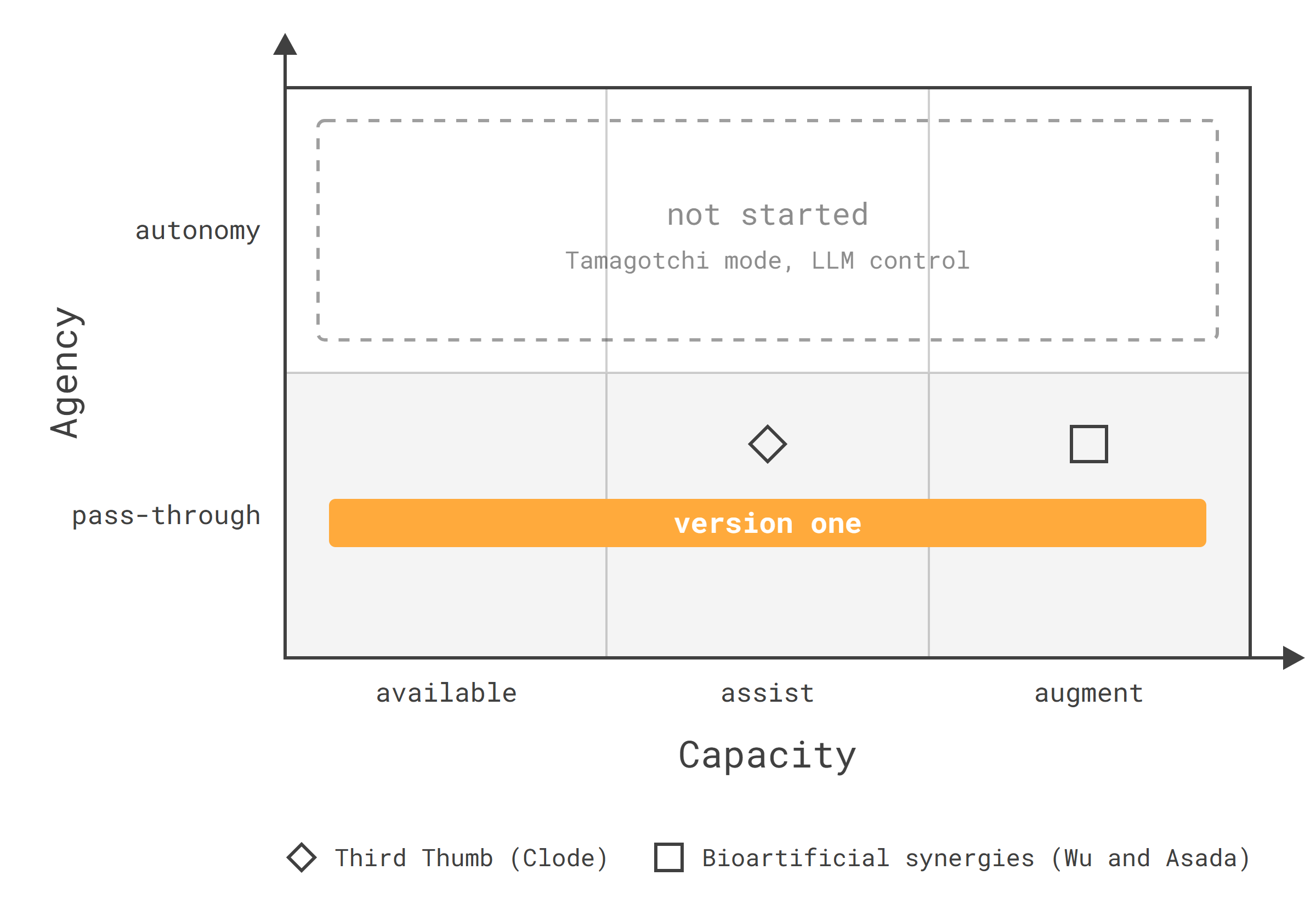
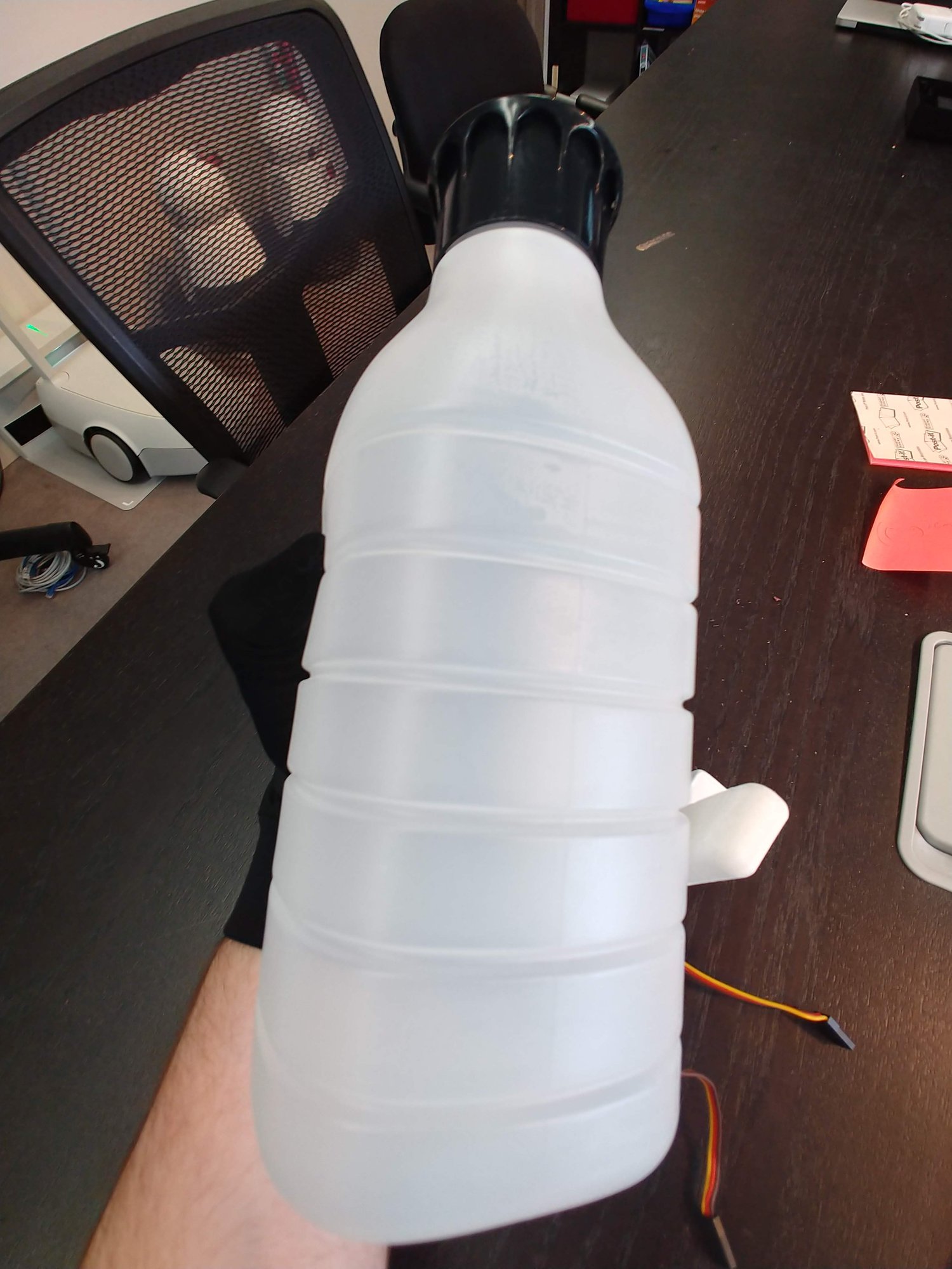
The two axes are independent. A pass-through finger can Augment (that’s the two-mug photo) and an agent finger can spend most of its day Available. The design questions live in the combinations. A pass-through finger that Assists is a tool the wearer learns to drive. An agent finger that decides on its own to Augment is a second party in the grasp, and the wearer has to trust it.
Version one is a pass-through. All a pass-through needs is a sensor glove and a mapping from hand posture to finger pose, and I had a semester stacked with classes and cobot research. An agent needs to see the object and read the wearer’s intent before it can decide anything. That means more hardware on the wrist and a lot more software behind it, and agentic control is not a solved problem now, let alone in 2019. Within pass-through, the finger can still reach all three capacities, as long as I’m the one deciding which.
Hardware, Version One
The hardware breaks into three subsystems. There is the finger, a sensing glove, and a wrist strap carrying the electronics.
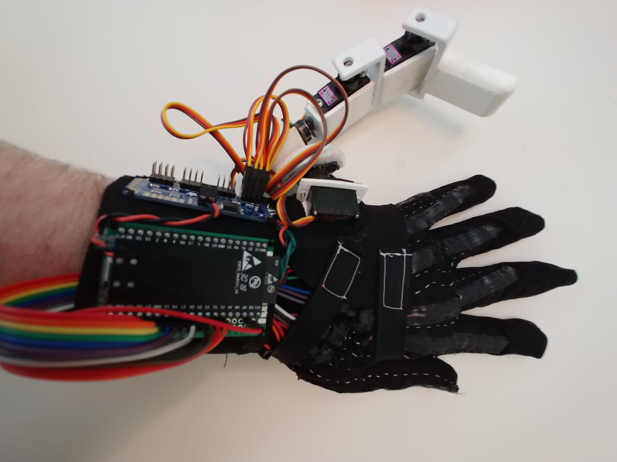
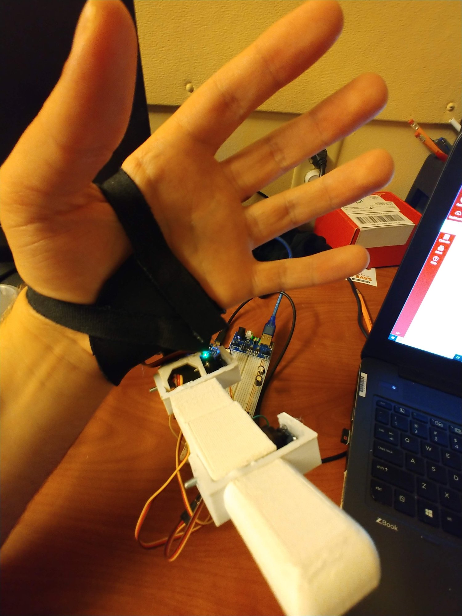
The finger. The finger is 3D printed from modular pieces and worn next to the pinky of my left hand, where it mirrors the position and joint structure of a thumb. A high-torque micro servo sits at each of its four joints and drives it directly. There is a rotation near the root where the finger meets the hand and bend joints down the rest of its length, and since the servos don’t care about anatomy, it has more range of motion than the thumb it copies.
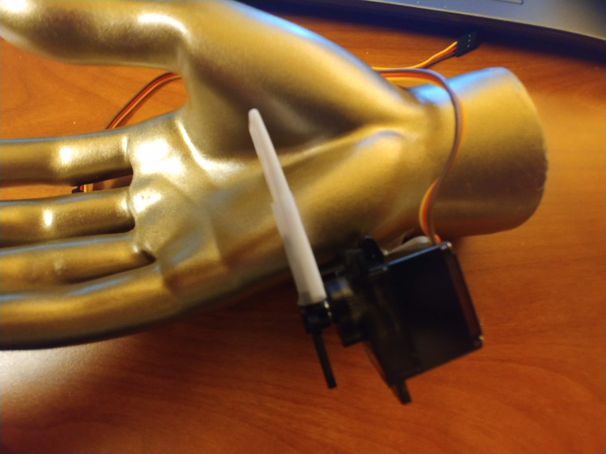
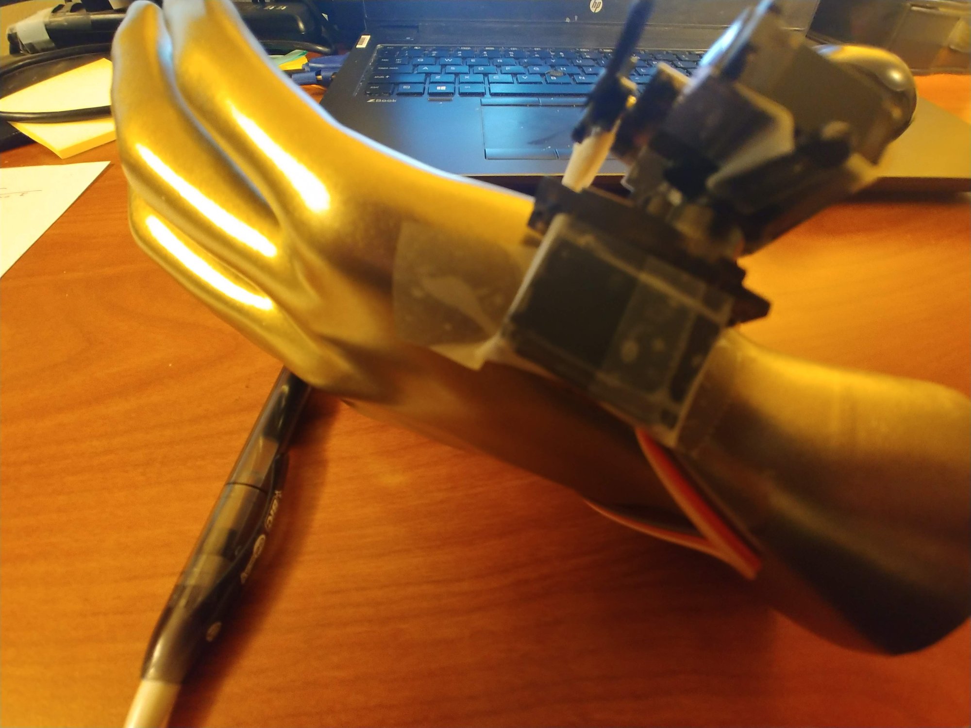
It started with three joints. Three is enough for small objects, but a grasp on something large or awkward needs support below the palm, so the fourth servo went in during the last two weeks of the course. Getting that rotation joint placed took a few tries. At the bottom of the finger it collided with my hand. In the middle it still collided. What finally worked was changing the angle the whole finger sits at, which cleared the collisions at the cost of a bigger finger that sticks out further from the hand. The piece that sets that angle I built out of broken 3D printed hinges, copious hot glue, and part of a Command hook taken from my wall.
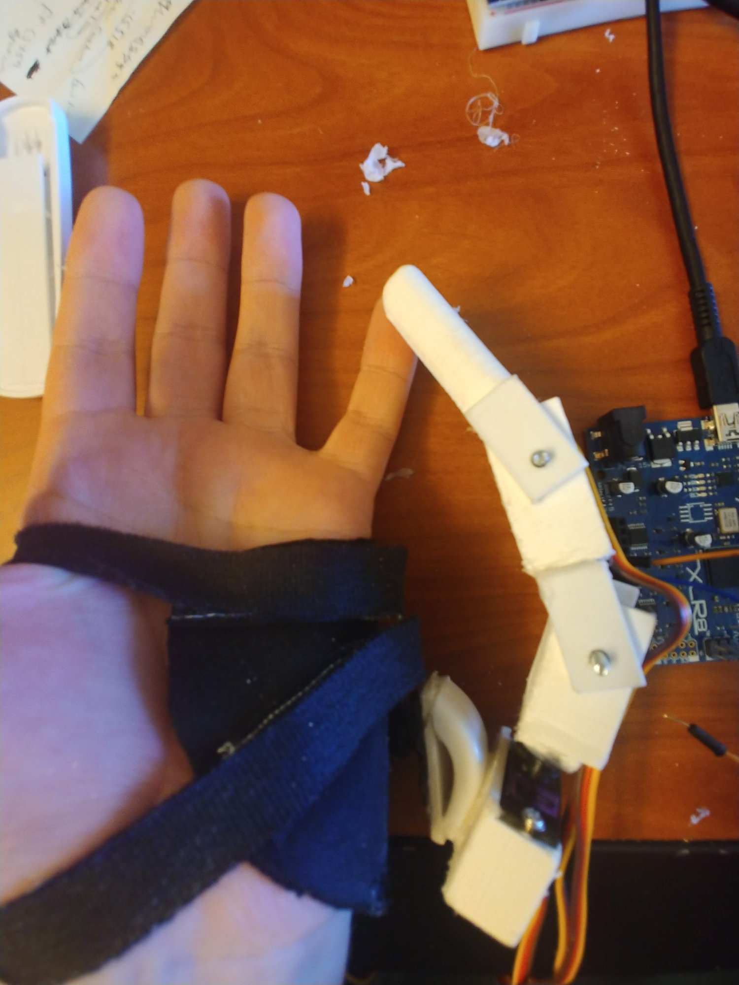
Direct drive was purely a proof-of-concept decision and it was a mistake. Every servo sits out on the finger where its weight does the most damage to the lever arm, and the servos do not have the torque to hold anything more than a light object. A future version should use some kind of linkage to move the actuator mass back to the base.
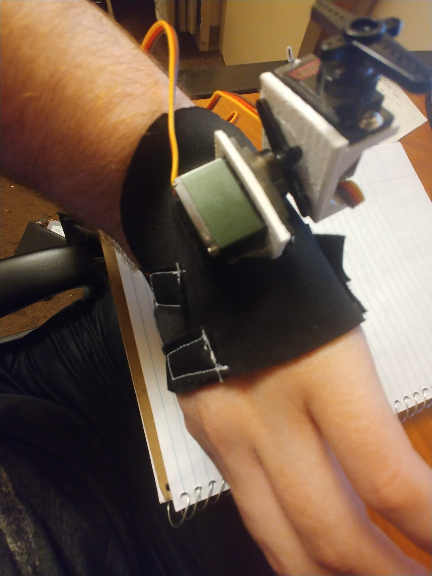
The finger mounts to a soft brace rather than to the glove. The brace is neoprene with a leather stiffener to kill the elastic bounce and several tucks sewn in so it conforms to the hand, cut in the shape of a wrist brace with two Velcro straps so it fits a range of hand sizes. The original idea was to modify a skateboard or snowboard wrist guard, but someone in class suggested a soft support brace instead so I would keep full wrist movement.

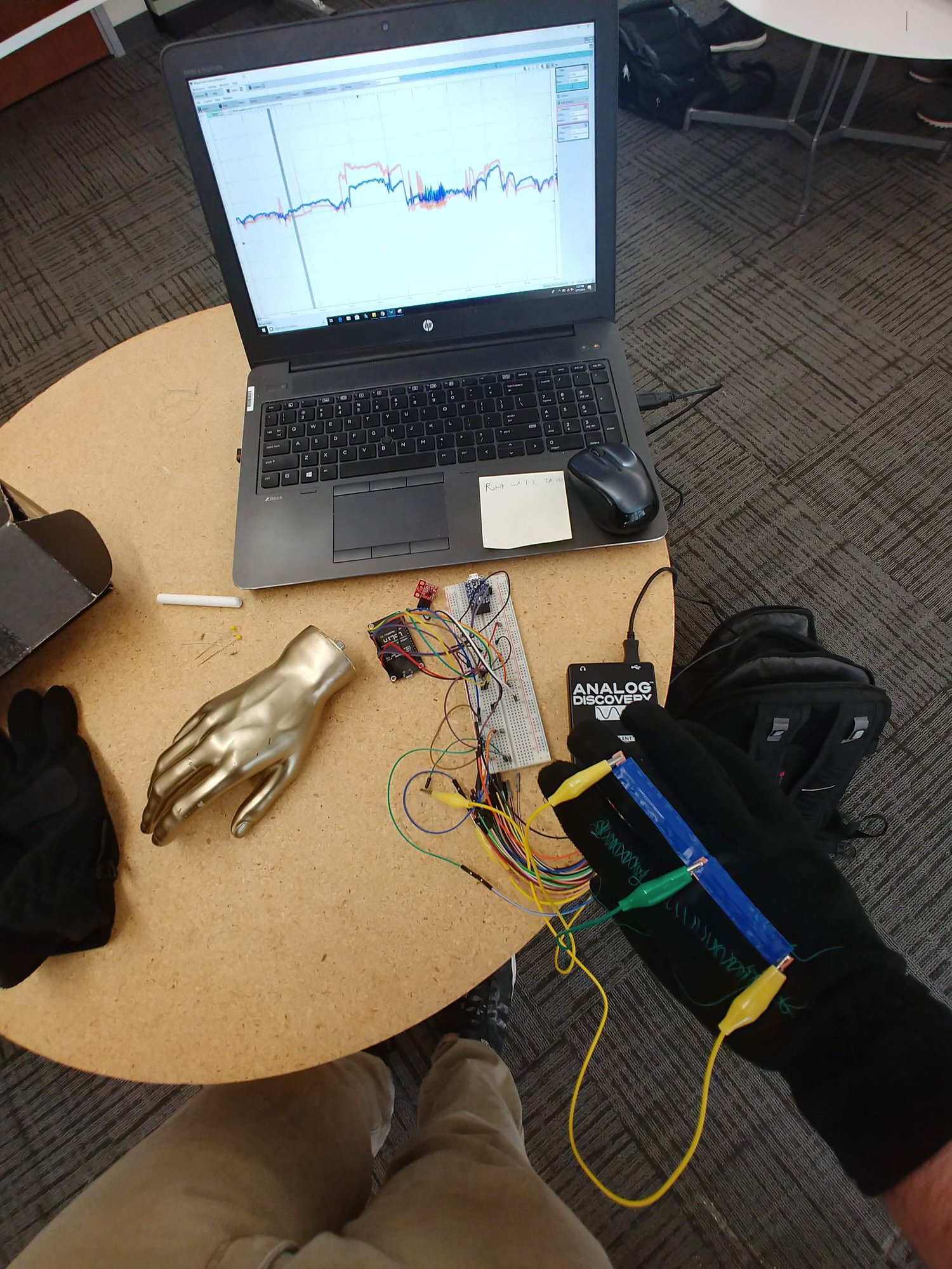
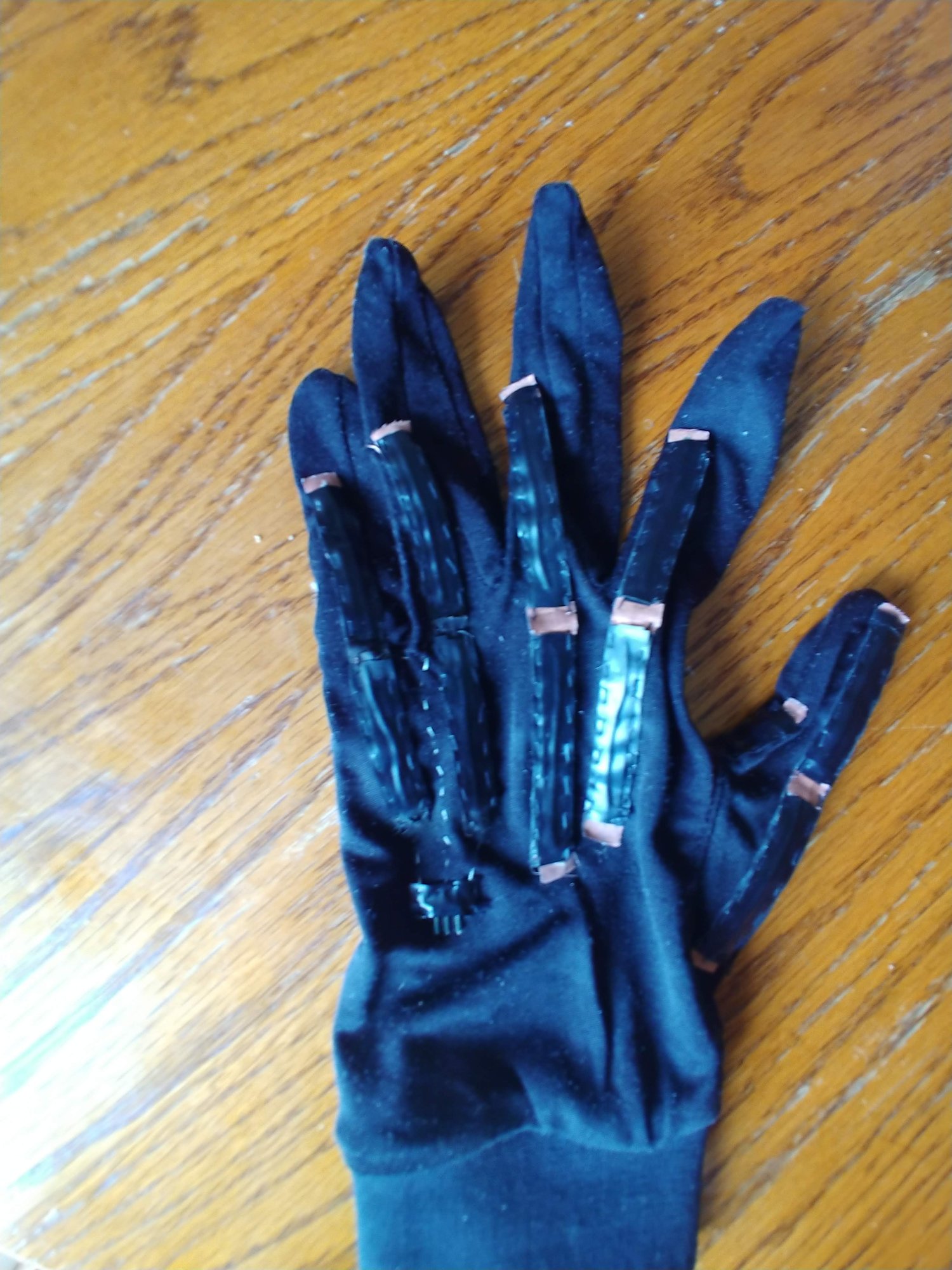
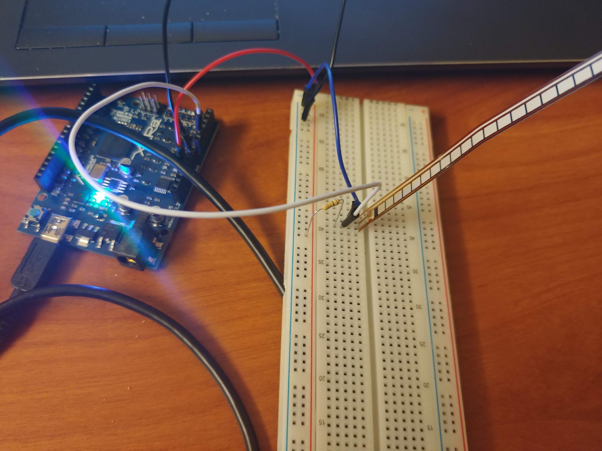
The sensing glove. For direct control I needed to know what my real fingers were doing. Commercial flex sensors are built on a flexible PCB that fights the glove rather than following the hand due to it still being fairly stiff (more on those later, since they end up saving the showcase). This was a wearable electronics course, though, and the instructor pointed us at Plusea’s DIY fabric flex sensors, so I made my own and sewed them onto a glove (over a mannequin hand, to keep the material supported). Each sensor is two runs of silver-nylon conductive thread with Velostat sandwiched between them. Conductive copper fabric on each end serves as connection tabs, with Bare Conductive ink to bond the thread to the copper. The wire-to-thread interface is a 2- or 3-pin male header with the thread tied and wrapped around the long end, secured with conductive ink, pushed through a piece of electrical tape, and hot glued.
Plusea’s design reads one joint per strip. I added a node in the middle of each strip that feeds in the voltage, so the two halves become two separate sensors sharing a supply node, and one strip down a finger gives you two joints. As I recall, the index, middle, and ring fingers got split sensors and the thumb and pinky got singles, eight channels in all, which is why the firmware enumerates its sensors in pairs (flex_0_0 and flex_0_1, flex_1_0 and flex_1_1, and so on) with room for more than were ever wired. Each channel is a voltage divider, the sensor in series with a 1 kΩ resistor to ground off the 3.3 V rail, selected through an analog mux and read by the ESP32’s ADC.
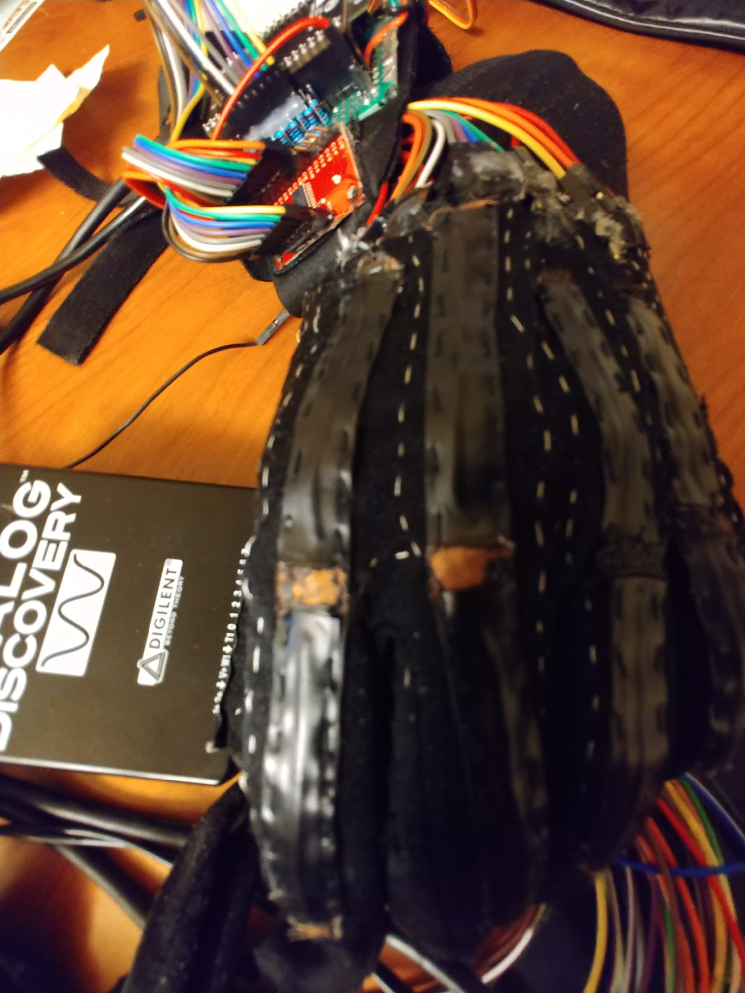
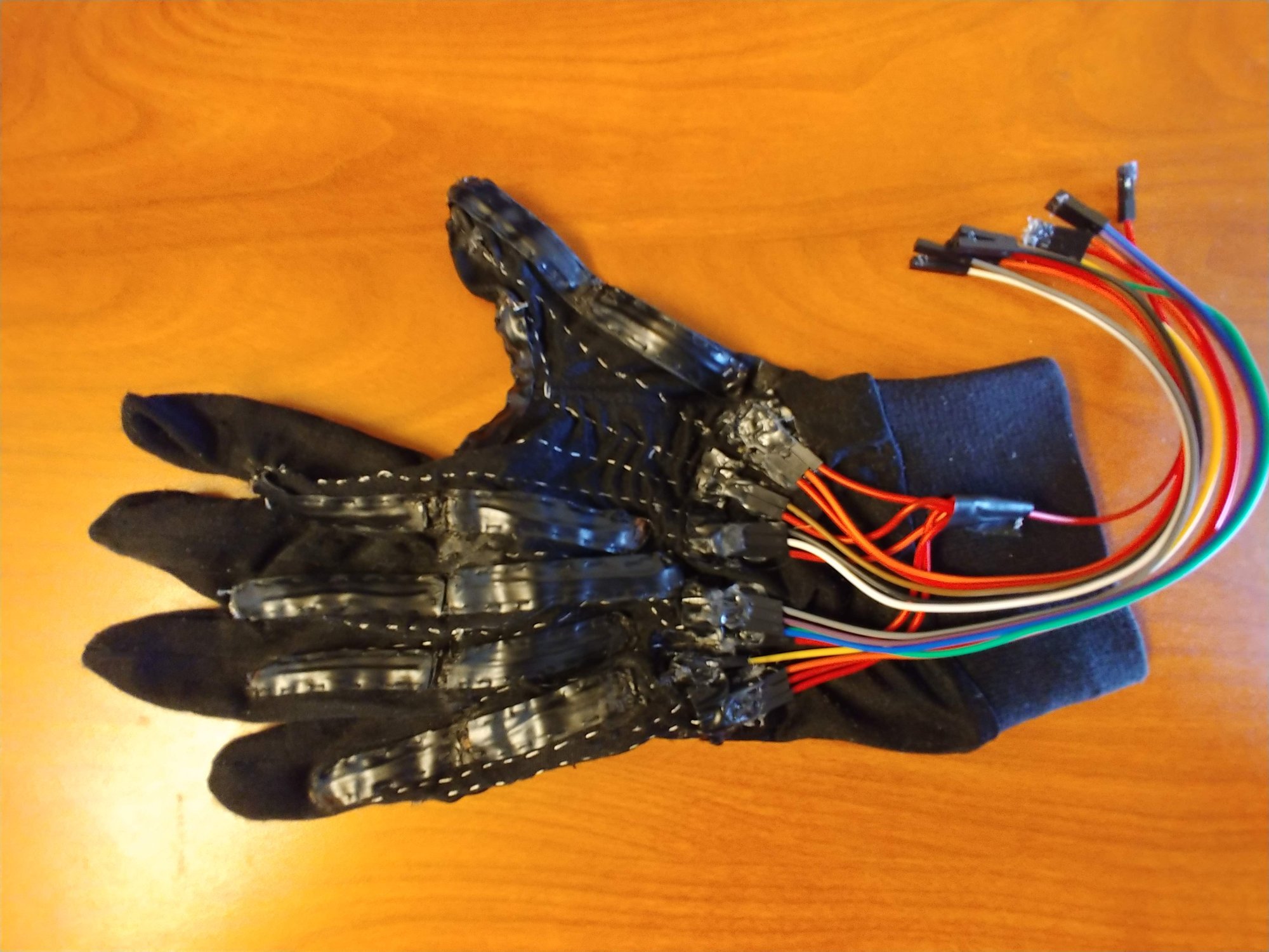
The wrist strap. I built the wrist strap to physically keep the glove and the finger aligned. Specifically, it stops the glove from shifting around while I move my hand. Unfortunately that makes it a bit uncomfortable to wear, since it can get rather tight.
Electrically the strap carries an ESP32 dev board running Arduino firmware, an Adafruit 16-channel PWM servo driver (a PCA9685 at I2C address 0x40) for the finger servos, and a 16-channel analog mux so the flex sensors share one ADC pin. At one point there was also an MPU9250 IMU (Inertial Measurement Unit) on the strap, later pulled off for a different project.
I bought the mux on a whim for another project, and it ended up saving the sensor side of this project. The ESP32 advertises two ADCs, but the second one is unusable once WiFi is up, and the first is flaky under the same conditions. I ended up debugging over Bluetooth, but WiFi was the long-term plan, so I could not build on ADC2. That left one good ADC pin, so every sensor goes through the mux.
The I2C servo board wasn’t the original plan either. The first version drove the servos’ PWM straight off the ESP32, and that went well (read not well at all). The ESP32 is a 3.3 V part and the servos wanted about 5 V. A 3.3 V logic level is just barely a logic high to them, right up until a servo starts drawing current, the rail sags on the shared USB hub, and the microcontroller’s IO sags with it. What that looks like in practice is continuous jitter with the occasional spasm, which is not what you want from something strapped to your hand. It was completely deterministic once I found it. I used an old 5 V Arduino clone for testing while I sorted it out, but the fix was the I2C servo board on its own USB supply, so the servos can’t brown out the ESP32.
Firmware
The firmware is deliberately kept as a simple relay. It samples the flex sensors, sets servo positions, and reports state back. All of the interesting control logic lives on a PC communicating over Bluetooth.
The API is JSON, one message per nul-terminated (\0) frame, over the ESP32’s Bluetooth Classic serial to the laptop, where the device advertises itself as TALTOSIOD-API, typo included. A DEBUG_MODE flag swaps in the USB serial port for bench work. The ESP32 was picked because it had Bluetooth and WiFi on board. WiFi was the plan for later and never happened.
The request types are what you’d expect from a relay:
joint_setwith ajoint_idand anangle, clamped to the joint’s limits (0 to 165 degrees on every joint, with per-joint default poses of 90, 75, 70, and 85 degrees on boot).joint_getandflex_sensor_getfor polling a single value.metadata_get, which returns the chip ID and firmware version.force_push_msg, which triggers the state dump on demand.
The firmware also pushes a full state_push message every 100 ms with every flex sensor reading (normalized to 0.0 through 1.0 off the 12-bit ADC) and every joint’s commanded angle. Sensors are sampled every 50 ms, with a throwaway analogRead before each real one so the mux has time to settle. Every request gets a JSON response, and malformed requests get an error object with the offending buffer echoed back, which saved me a lot of time when I was writing the PC side.
The PC Side
The PC ran a machine learning model that mapped flex sensor readings to joint angles for the robotic finger. The inspiration was Wu and Asada’s bioartificial synergies work. Rather than hand-authoring a mapping from “my hand is doing X” to “the finger should do Y,” you record the wearer’s hand posture alongside the finger posture they want and let a model learn the relationship. My servos were dumb, though. They take a position and never report one back, so I could not move the finger by hand and record where it ended up. Instead I commanded each joint from the laptop and captured the commanded angle. Version two should have a compliant training mode, where the finger goes limp, I pose it where I want it, and it records that.
On the laptop side I wrote a few Python scripts. A training CLI dumped sensor readings and joint states to CSV while I posed the finger and my hand together. A model generation script fit a model to that CSV and pickled it. A multi-threaded runner read state off the serial port, ran the model, and commanded the finger. None of that Python ever made it into the repo, and now it’s lost to time.
For the mapping itself I tried linear regression, AdaBoost random forest regression, and a neural network. Each was a supervised scikit-learn model going straight from raw sensor readings to joint states. The regression approaches used four models, one per joint, while the neural net produced all four joints from one model. PCA on the sensor data made no meaningful difference. That is not the same experiment as the synergies paper, where Wu and Asada ran PCA over the human hand and robot finger postures together and let the shared components carry the coupling. I only reduced the inputs, and my small hand-collected sample would not have supported much either way. It also fits with why they moved to partial least squares in the follow-up, since PCA on the inputs alone knows nothing about the outputs it is meant to predict. A moving average on the inputs helped the regression approaches and did nothing for the neural net, which was already stable. Averaging on both the inputs and the outputs gave a stable but laggy finger. So, yeah, neural net it is.
What the model actually learned is easy to describe. A fully closed hand brings the finger’s tip down to rest on my fingers, the way a thumb sits on a closed fist. A fully open hand stretches the finger out, assuming a large object is coming. In between it moves to anticipate the size of whatever is being grasped, whether or not anything is actually there. The flex sensors have no way of knowing whether an object is there. Perhaps version two needs a camera.
The problem is different grasps can produce near-identical flex sensor signatures while needing completely different finger poses. Perfectly valid-looking training data would tank the model because the sensors simply do not carry enough information to tell those cases apart. At the time I noted that as “needs environmental context sensing.”
The ROS Layer
I also started building a ROS layer for the device, partly as a learning exercise (this was the same period I was getting comfortable with ROS on the lab’s UR3e) and partly as the foundation for version two. The idea was to build out several control strategies in simulation while working on a better finger design, so that when the hardware was ready the software would be too.
The repo is structured as a multi-package ROS workspace:
taltosoid_hardwareholds the Arduino firmware, the sensor experiments, and the STL meshes.taltosoid_driverhas the URDF, an RViz config, and the driver nodes.taltosoid_controllaunches rosbridge and a small web server for a browser-based control page.taltosoid_srfis the metapackage tying it together.
The URDF describes the finger from a base_link through the root, a rotation link, two finger segments with hinges between them, and a tip with an end-effector target frame, all with the printed STLs as visual and collision geometry. The driver node is a “fake” driver for RelaxedIK, the same solver from my UR3e motion playground. It subscribes to /relaxed_ik/joint_angle_solutions, repackages the angles as a JointState, and publishes them so RViz can animate the finger. Drag a target around and watch the finger chase it.
The hardware driver that would send those solutions to the real finger is a Python file containing pass. The browser control page is an index with one link to a “Direct Slider Control” page that is an empty file. All good ideas that I really need to work on again. I recall a paper deadline landing about then, and the ROS work never picked back up.
The Showcase
The course ended with a public showcase and a poster. The glove died on the showcase floor, as described above, so the demo ran on a simplified replacement I put together in the time left, two of the commercial Adafruit flex sensors strapped to my thumb and index finger and driving the finger through a neural net I respun on the show floor. It demonstrated the intuitive control well enough. Nobody, including me, would have called it finished.
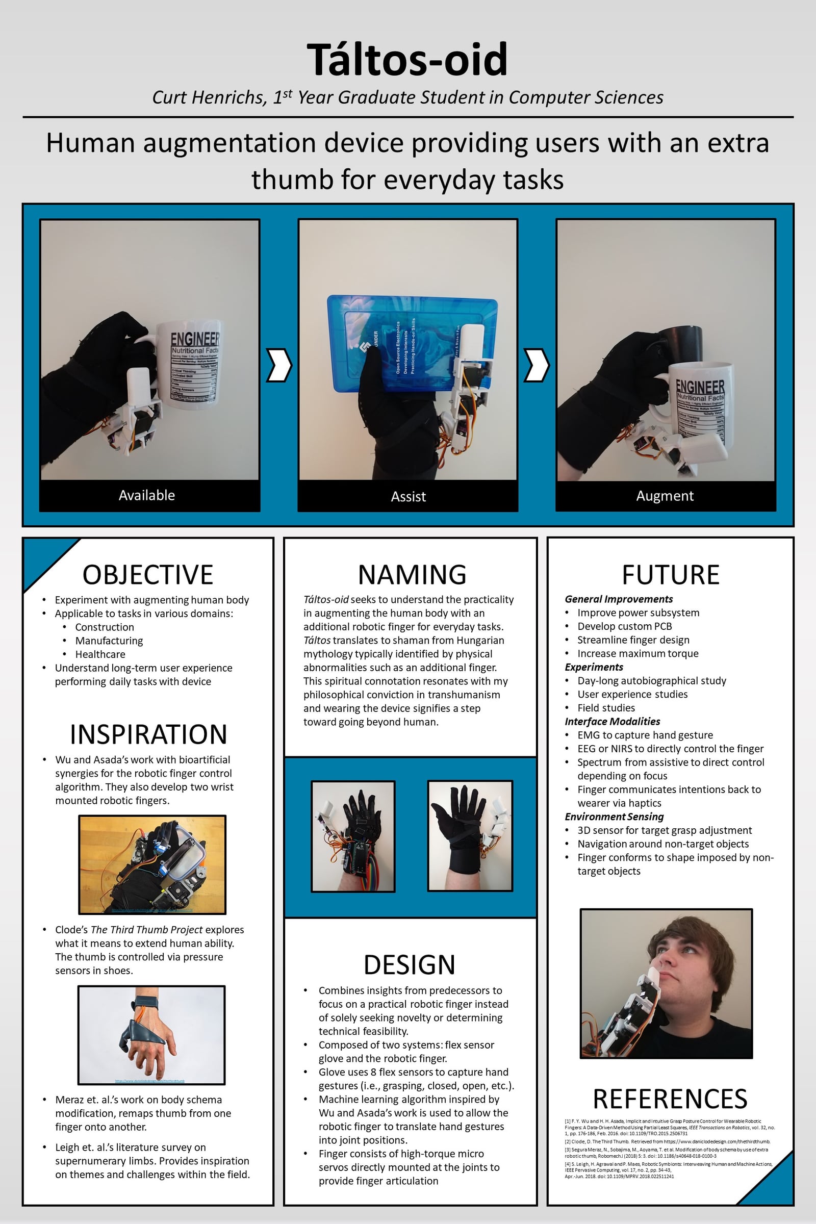
In the final write-up I scored the project 8.5 out of 10 against my own expectations, and the missing 1.5 was the user study I never ran. The whole point was to find out what living with the device is like, and the course, well, ran its course before I could investigate that (not that the version one finger would have held up).
Wearing It
The photos make it look better than it feels. When I put the finger back on in 2024 to restart the project, I wrote down every discomfort while it was fresh, and the list isn’t short.
I put my finger on today as I am restarting the project and wanted to remind myself of the wearability. First as I type, my wrist rests awkwardly, this is due to the mounting point of the finger. Second blood circulation at my thumb and index finger are not great due to the mounting Velcro straps to hold the flex sensors. The sensors themselves dig into my skin at the finger tips and at the base. Most prominent is the digging in on the index finger. As I wear the device the compute strap has a wire under that digs in as well.
The finger mounting point is awkward to type on a keyboard and the sensor mounting makes it awkward to type on a phone. Taking pictures of the hand is also difficult.
I am also not pleased with the Velcro finger straps removing sensation on the finger tips (often the straps make contact with the grasped object first). I also am not a fan of the open wires (and more generally the bulk) of the compute module on the wrist. Note too that this is without battery which adds considerable weight.
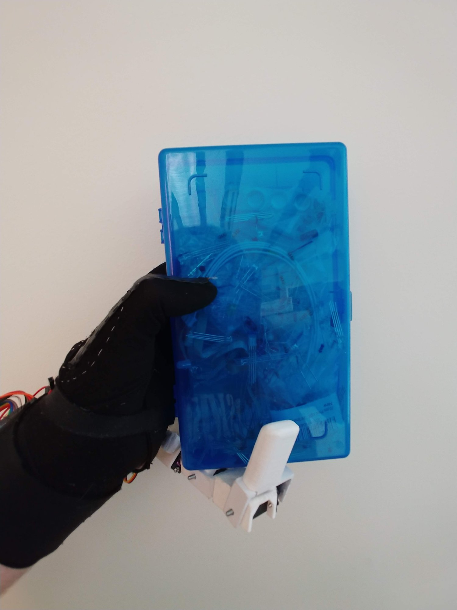
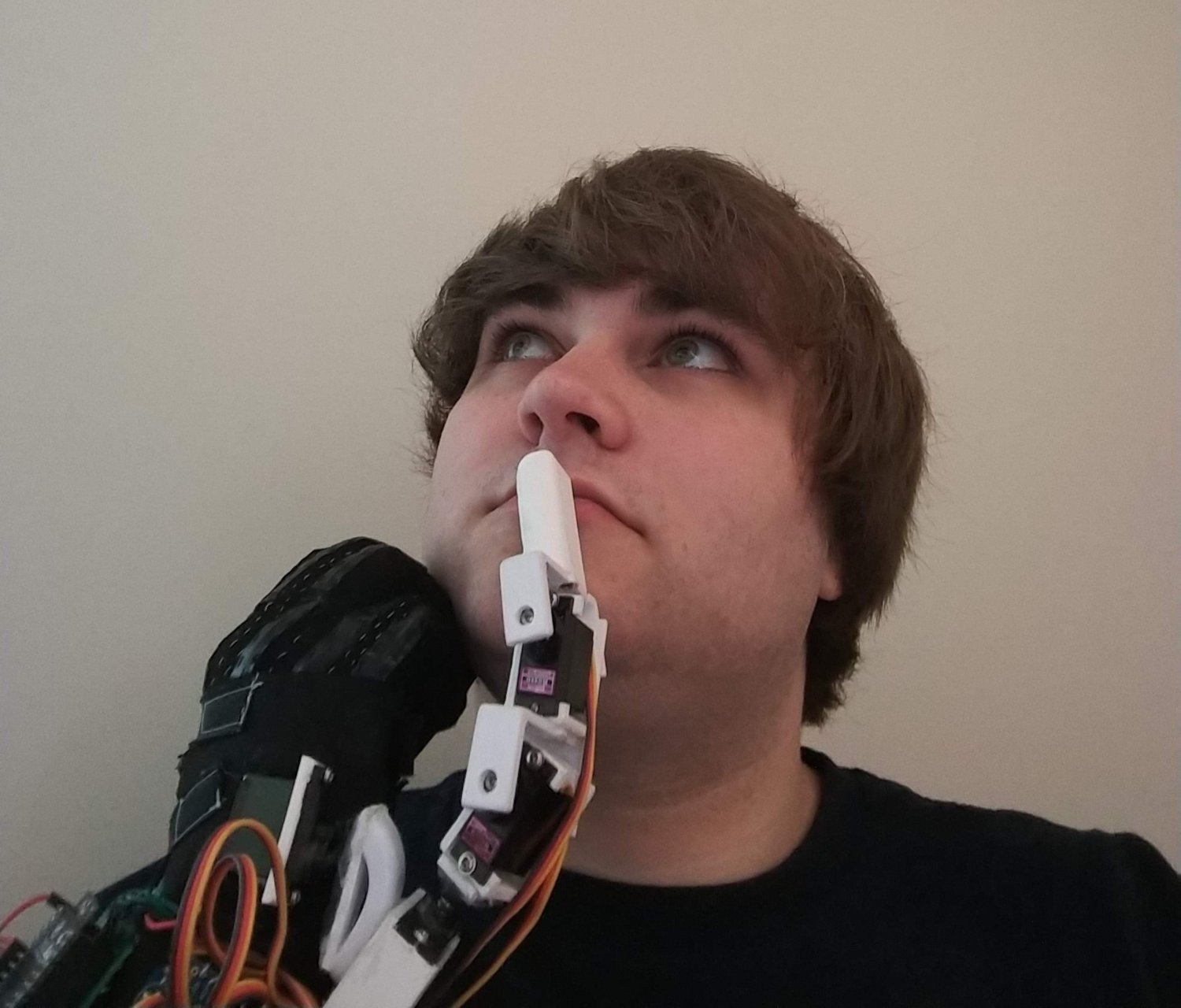
The finger itself is worn out and would need real rework. My note to myself at the time was to keep the current finger for an early evaluation, rebuild the glove, and redo the control electronics, with a budget of about a hundred dollars for a “version 1.2,” then a couple hundred more for a proper version two with a better mounting scheme.
Future Plans
The plan for evaluating this thing was an autobiographical study. Wear it for a full day and see what breaks. In autobiographical design the researcher is also the user, so the person building the device is the one living with it and writing up what happened.7 A sample of one is still a sample of one, and the people who use the method are upfront about the tensions that creates.8 But there was one prototype, it fit my hand, and the problems worth finding sit behind the obvious ones. Nobody reaches them until they have put up with the ordinary breakdowns of adding a supernumerary limb first.
The protocol I drafted was two days. Day one, a normal day, with a camera on my left shoulder pointed down at my hands and a second camera on my forearm, to capture how I actually use my hands. Day two, the same cameras plus the finger in a limited actuation mode, where two flex sensors on my index finger and thumb drive the robotic thumb’s position through a simple heuristic. Then code the video for hand activity themes and wearability breakdowns. Neither day ever got recorded.
Below are the improvements needed for version two:
- Improved power system and a custom, compact controller PCB.
- Higher-torque, more compact finger with the actuators at the base.
- Alternative control inputs such as EMG, NIRS, or vision.
- Communication from the finger back to the wearer, haptic or otherwise.
- The finger has no way to tell me anything. I find out what it is doing by looking at it.
- Environment sensing for 3D grasp targeting, collision avoidance, and context-aware posing.
- Augmentation control strategies beyond direct mirroring.
- Mirroring my thumb is the easy version. An extra finger should do more than copy one I already have.
- LLM control.
- Newest on the list, and the one that jumps straight to the autonomy end of the agency axis. Version one only ever mirrors what my hand is already doing, but put an LLM in the loop and the finger is the one deciding when and how to act. That stops being a control problem and turns into the social one.
- Tamagotchi mode.
- Treat the finger as a pet rather than a tool. Give it moods and needs so there is a reason to keep wearing it, since long-term wear is the hard part of studying this thing.
Conclusion
The finger works. It moves off my own hand posture through a model I trained rather than something hard-coded. The rest of the lessons from version one were hard fought, each by a specific failure mode. The glove chemistry was wrong (it literally dissolved during demo) and the direct drive servoing wastes torque on hoisting itself around instead of manipulating objects. The mounting is uncomfortable enough that I would not get through a normal day wearing it.
The question I started with is still open. Answering it means living with the device for longer than a demo, and the hardware has to be tolerable first. So version 1.2 is a new glove and a new control board. The part I actually want to build is a finger that decides things for itself, and I have not written a line of it yet.
While I was debugging that servo jitter, my log says I “banished the finger to a plastic box so that it would not make a freedom-focused break for the edge of the desk.” I know it was a voltage sag but I have been thinking about why I wrote it that way ever since, and that turned into its own reflection post here.
Thanks for reading. Check out my GitHub repo. Stay tuned and keep building.
Footnotes
-
The logs are filed under InGlove, a gesture-control glove for home automation that I started the semester on as a team project before splitting the finger off as my own. My sections are the ones labeled “Curt,” from post #3 on. ↩
-
F. Y. Wu and H. H. Asada, “Bio-Artificial Synergies for Grasp Posture Control of Supernumerary Robotic Fingers,” Proceedings of Robotics: Science and Systems (RSS X), Berkeley, CA, Jul. 2014. doi:10.15607/RSS.2014.X.027 ↩
-
F. Y. Wu and H. H. Asada, “Implicit and Intuitive Grasp Posture Control for Wearable Robotic Fingers: A Data-Driven Method Using Partial Least Squares,” IEEE Transactions on Robotics, vol. 32, no. 1, pp. 176-186, Feb. 2016. doi:10.1109/TRO.2015.2506731 ↩
-
D. Clode, The Third Thumb. daniclodedesign.com/thethirdthumb ↩
-
N. Segura Meraz, M. Sobajima, T. Aoyama, and Y. Hasegawa, “Modification of body schema by use of extra robotic thumb,” ROBOMECH Journal, vol. 5, no. 3, 2018. doi:10.1186/s40648-018-0100-3 ↩
-
S. Leigh, H. Agrawal, and P. Maes, “Robotic Symbionts: Interweaving Human and Machine Actions,” IEEE Pervasive Computing, vol. 17, no. 2, pp. 34-43, Apr.-Jun. 2018. doi:10.1109/MPRV.2018.022511241 ↩
-
C. Neustaedter and P. Sengers, “Autobiographical design in HCI research: designing and learning through use-it-yourself,” Proceedings of the Designing Interactive Systems Conference (DIS ‘12), 2012. doi:10.1145/2317956.2318034 ↩
-
A. Desjardins and C. Ball, “Revealing Tensions in Autobiographical Design in HCI,” Proceedings of the 2018 Designing Interactive Systems Conference (DIS ‘18), 2018. doi:10.1145/3196709.3196781 ↩