ESP8266 Hacked Grow Light with Okos Polip Device-to-Cloud Service
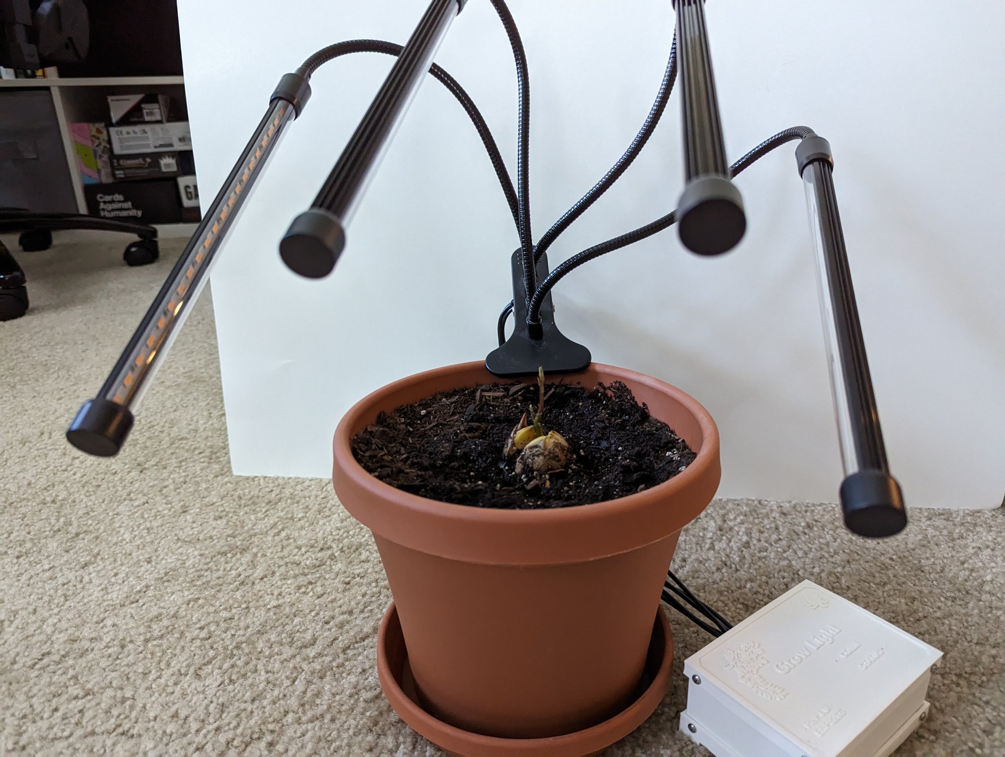
My avocado tree started life under a cheap clip-on grow light from Amazon. The tree is five years old now and much grown. Back in my 2022 home automation post I put the grow light first in line for hacking. Every time it got unplugged it forgot its settings and I had to press the buttons all over again. Also, the whole point of collecting plant data was to have something decide when the light comes on, and that something can’t press buttons.
So this is that hack. Same trick as the KOIOS air filter hack. The stock controller stays put and keeps doing its job, and an ESP8266 gets wired in beside it to press the buttons for me and peek at the LEDs to see what happened. It took three sittings spread over a year (I was working on the backend service and a day job in between). Below I will go through the hardware first, in the order it happened, then the firmware.
Hardware
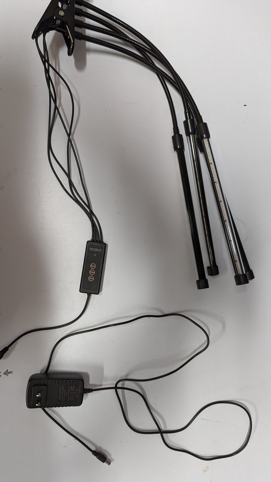
The stock grow light is a generic clip-on unit configured as follows:
- 12V DC wall wart into an inline controller on the cord
- Four flexible LED arms off the controller, driven as two channels (A and B)
- Three buttons on the controller. Switch, Dimming, and Timing
- Switch cycles Off, both channels, A only, B only
- Dimming steps through five brightness levels
- Timing steps through off, 3, 6, and 12 hours
- A red and a blue LED show the timer. Red is 3H, blue is 6H, both is 12H (it says so on the label)
- One small PCB inside. Buttons and LEDs on one side, the brains on the other
Teardown
Time to crack open the controller and see what we are working with.
-
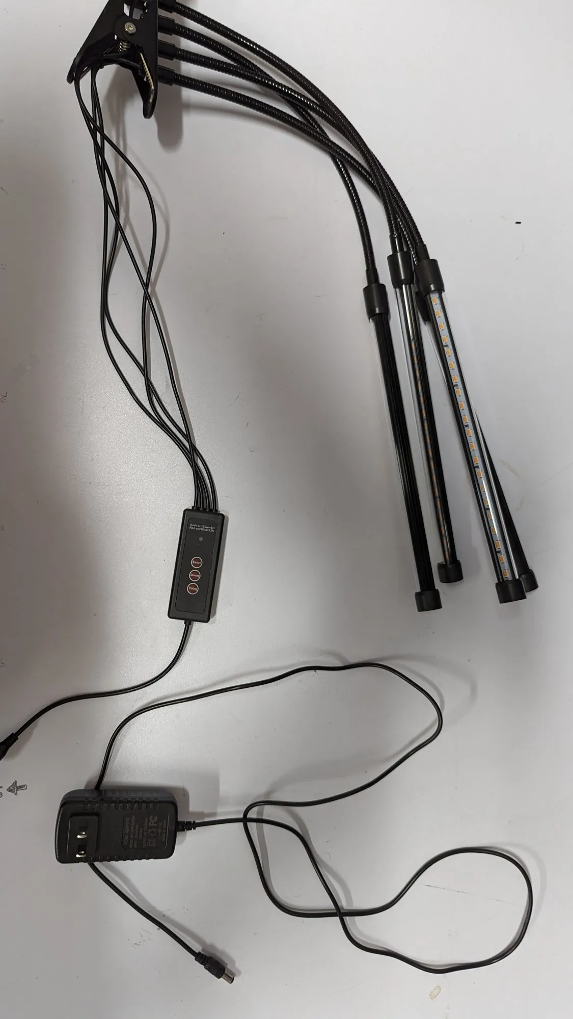
The whole grow light out of the box. Everything runs through the little controller in the middle of the cord.
-
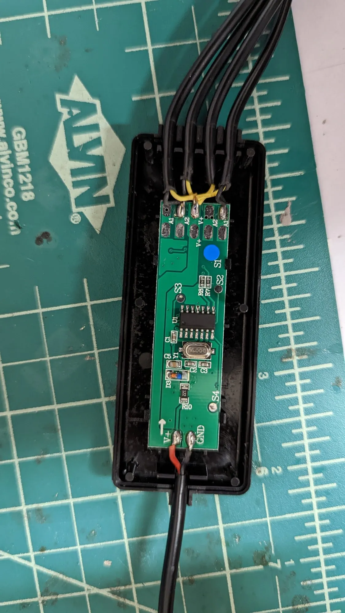
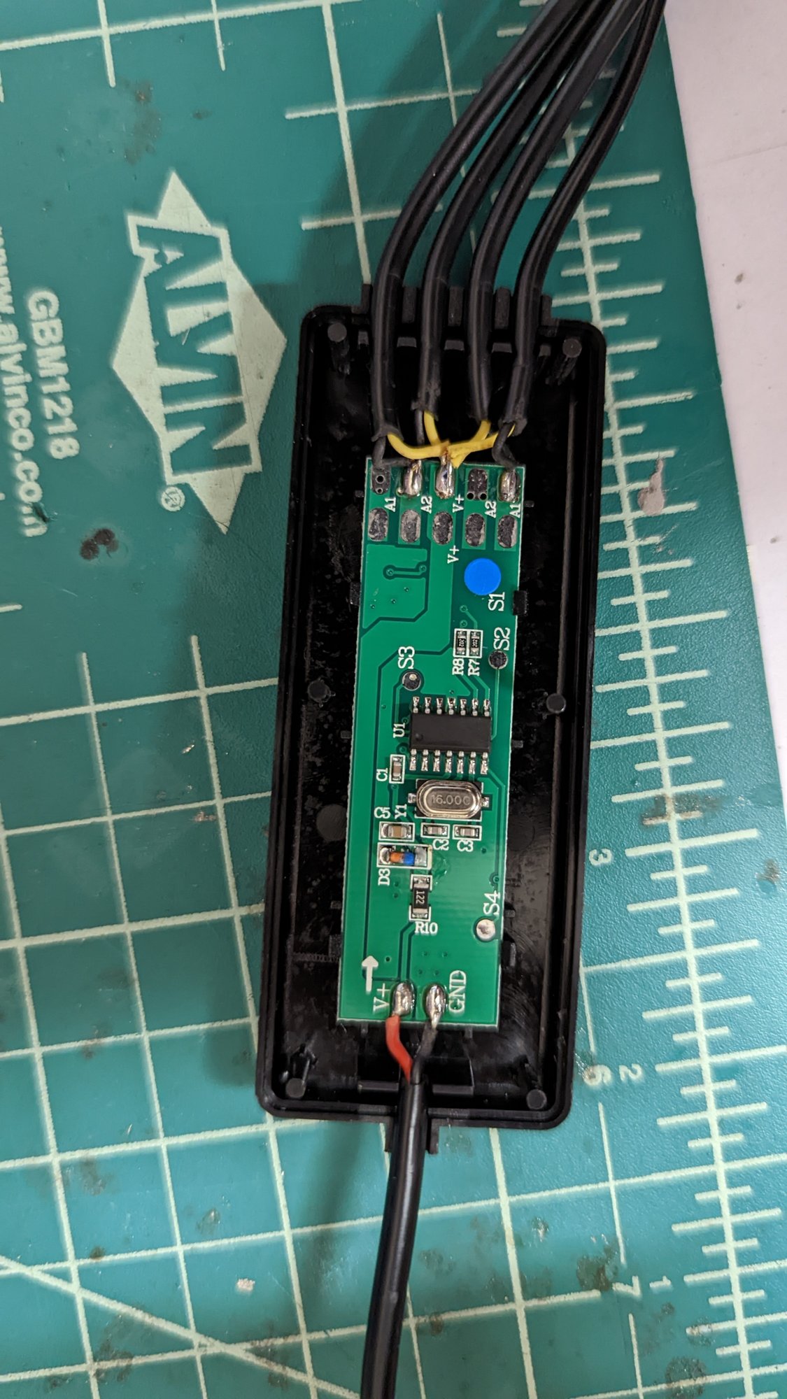
The controller shell comes apart with no screws. One small PCB inside.
-
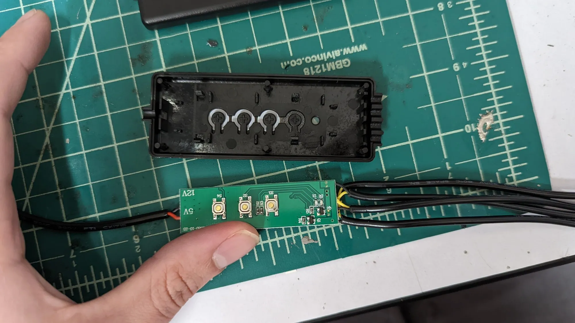
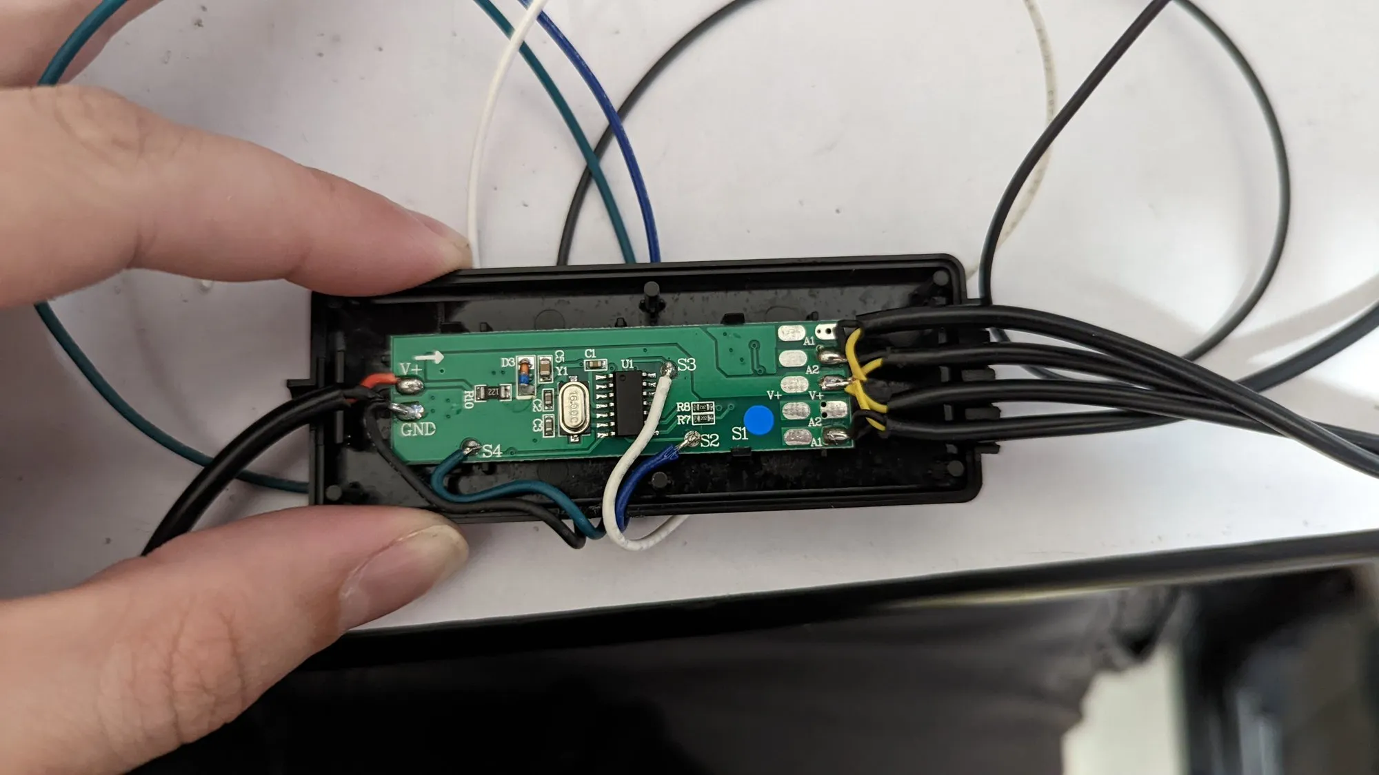
One PCB, two sides. The buttons and the indicator LEDs face the shell, and the microcontroller that drives the arms lives on the back of the same board. Huh. Compact.
-
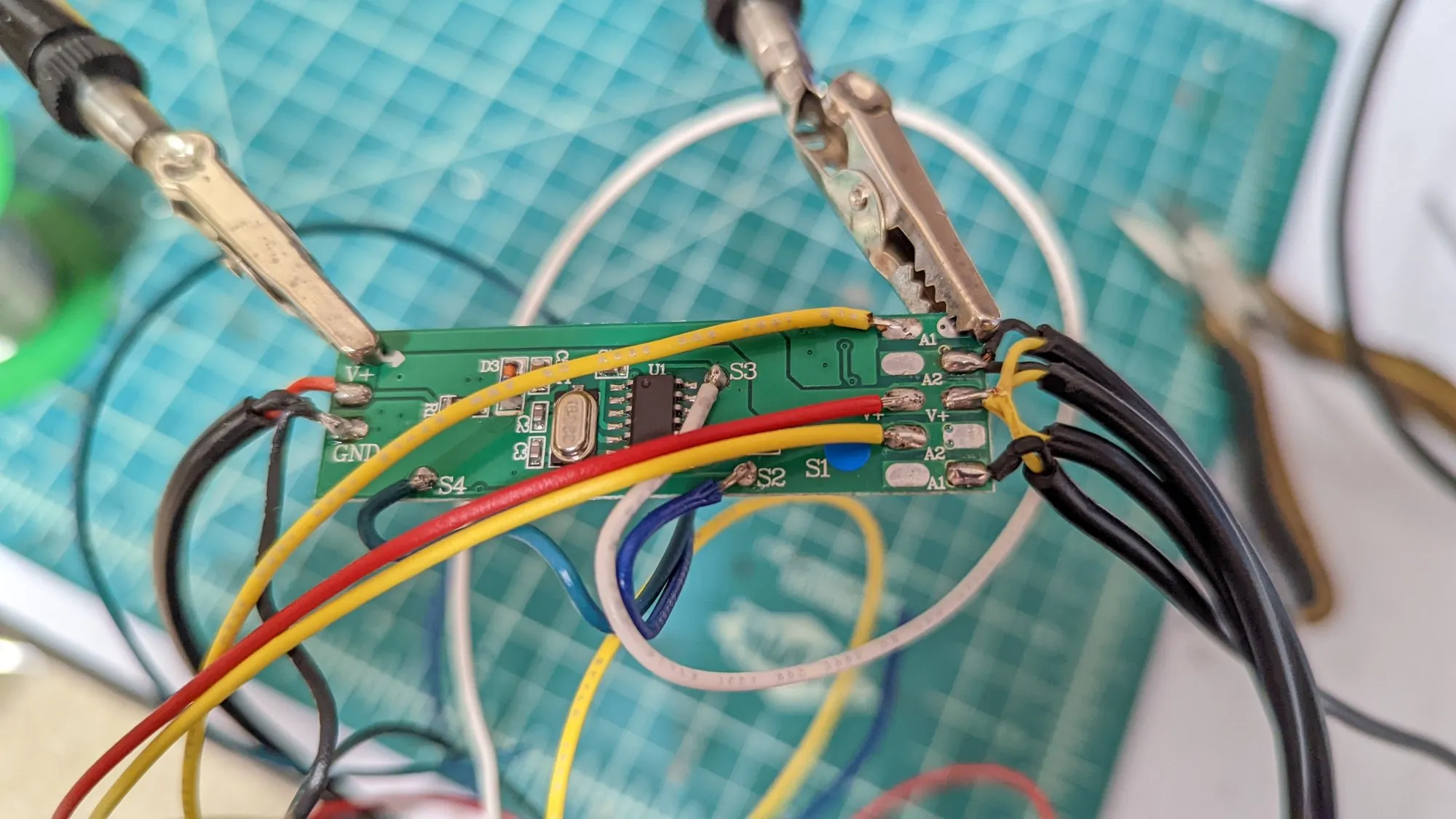
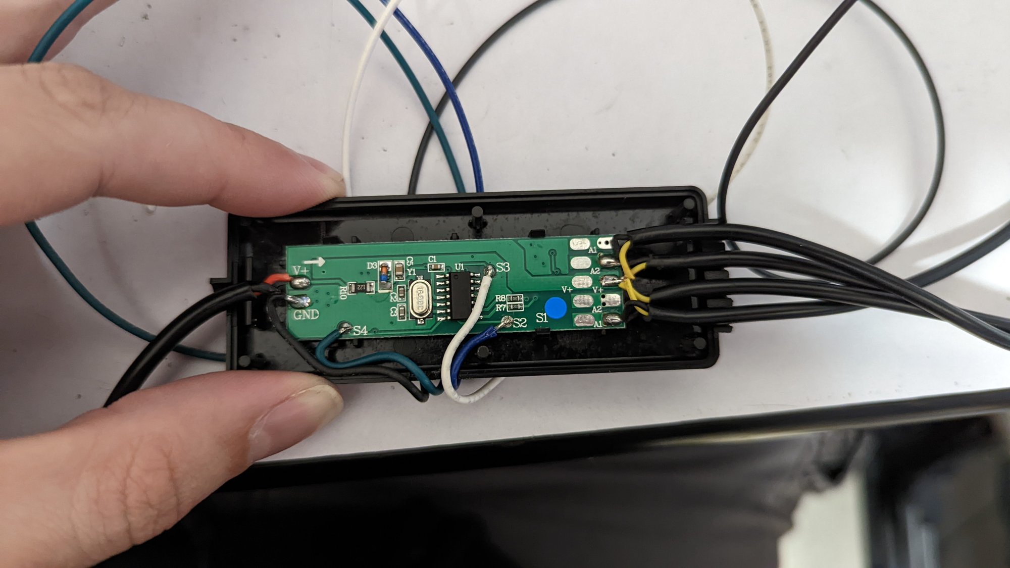
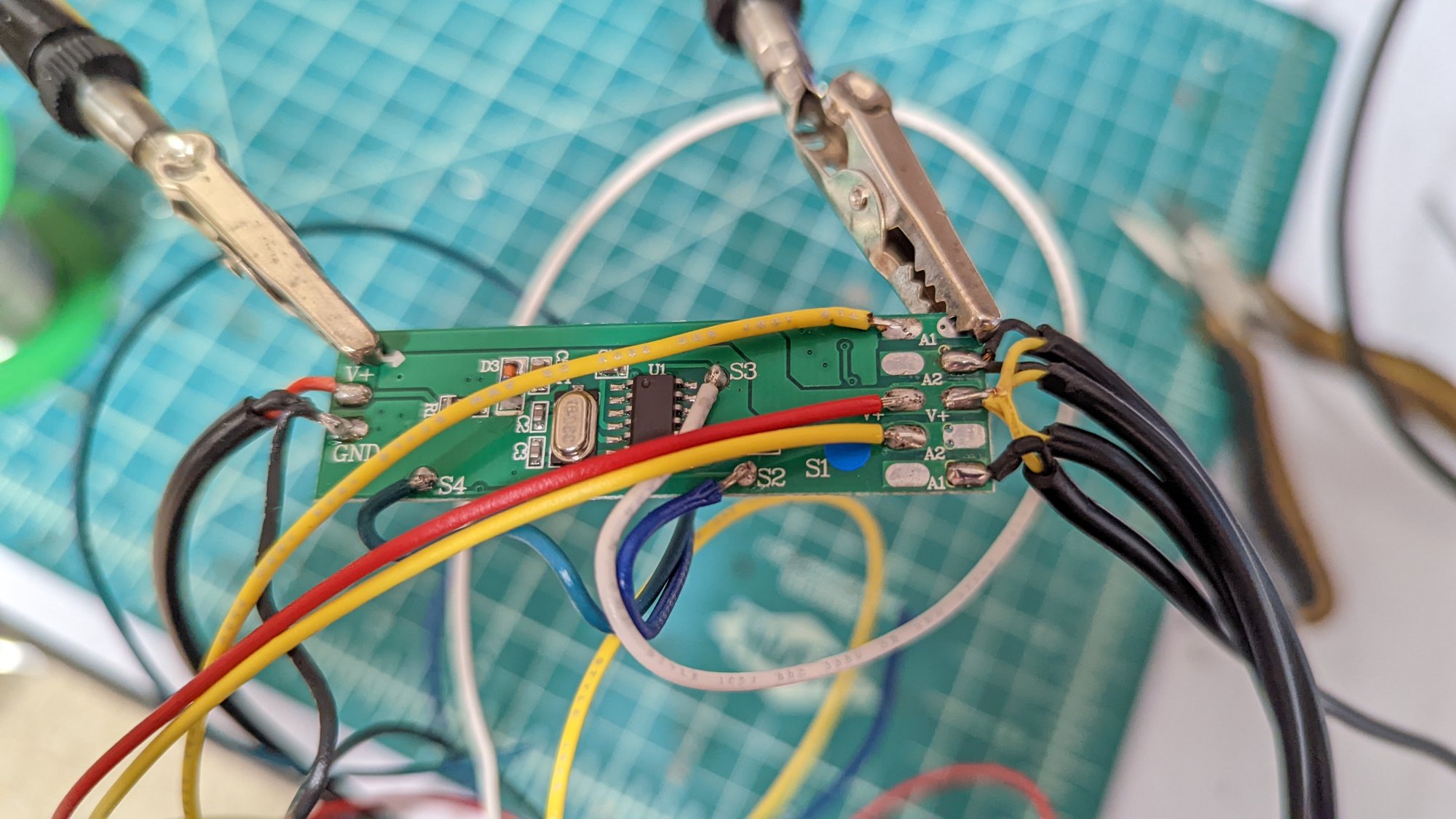
Helping hands (well, alligator clips) hold the board still while hookup wire gets soldered onto every pad I cared about. Power, the three buttons, and the arm channels.

Signal Extraction
With wires on the board it was time to poke at it and see what we are working with. Good news first. The buttons work exactly like the air filter’s.
The buttons are easy. Each one is a pad pulled up to 5V that goes to ground on a click, and a fast click to ground jogs the controller one step through that button’s cycle. So each button pad gets two wires. One to a MOSFET so the ESP8266 can click it, and one back to the ESP8266 so it can see the click.
Our first wrinkle is that the LED arms are PWM dimmed. The two channel lines are a square wave, not a level, so reading them straight into a GPIO gets you a mess. You would need a timer to recover the duty cycle. Hmm, a second wrinkle is that the grow light’s built-in timer has no output at all except its two indicator LEDs. So those LED lines get tapped too.
| Wire | Pad | What it is |
|---|---|---|
| White | S3 | Power button |
| Blue | S2 | Dimming button |
| Green | S4 | Timing button |
| Yellow (x2) | Channel A, Channel B | PWM drive to the arms |
| Yellow (x2) | Timer LEDs | Red (3H) and blue (6H) |
| Red, black | 12V, GND | Supply |
The stock controller still drives the arms and runs its own little state machine. The ESP8266 is just a very patient finger that clicks the buttons and squints at the LEDs to see what happened.
The Interface Board
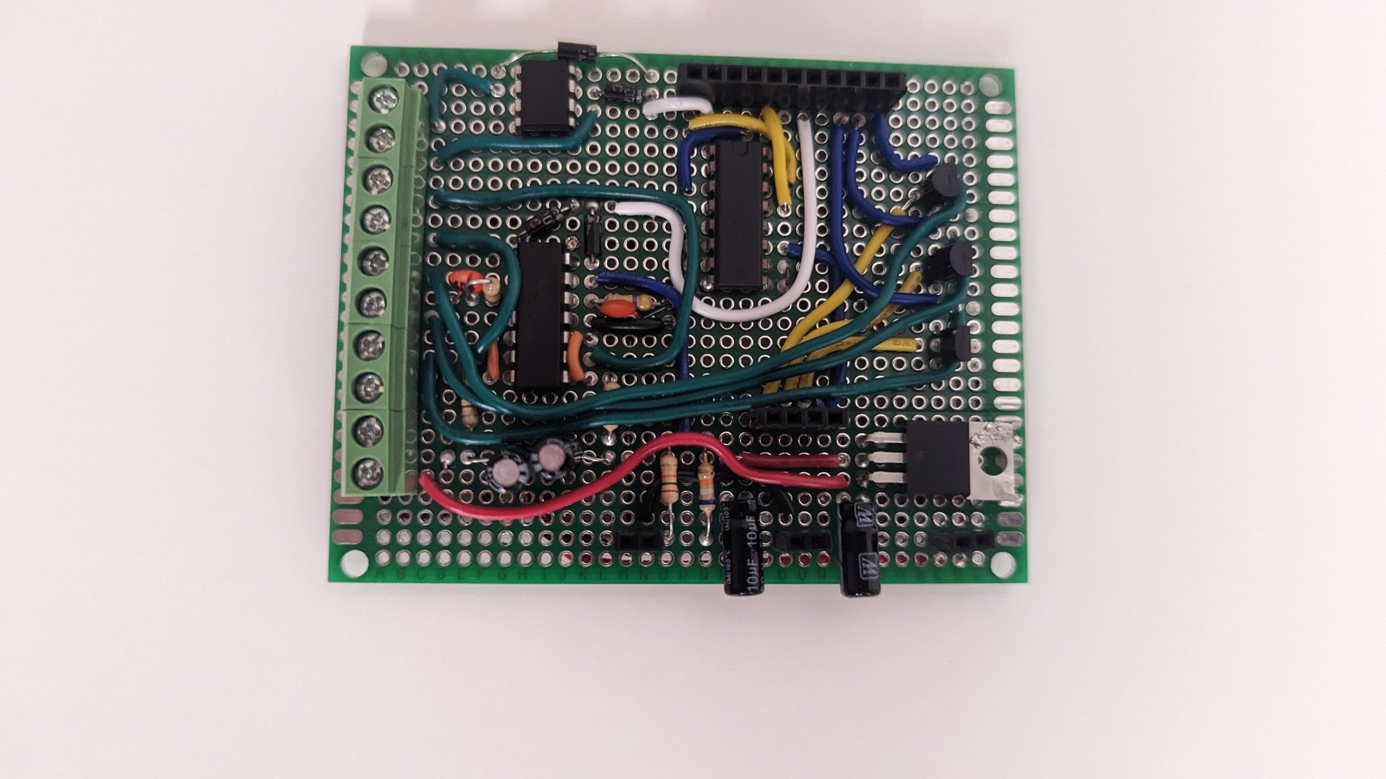
Time to build some new hardware. I split it into two boards. A perfboard base carries the interface circuit and screw terminals for the ten-wire harness, and a NodeMCU daughterboard stacks on top.
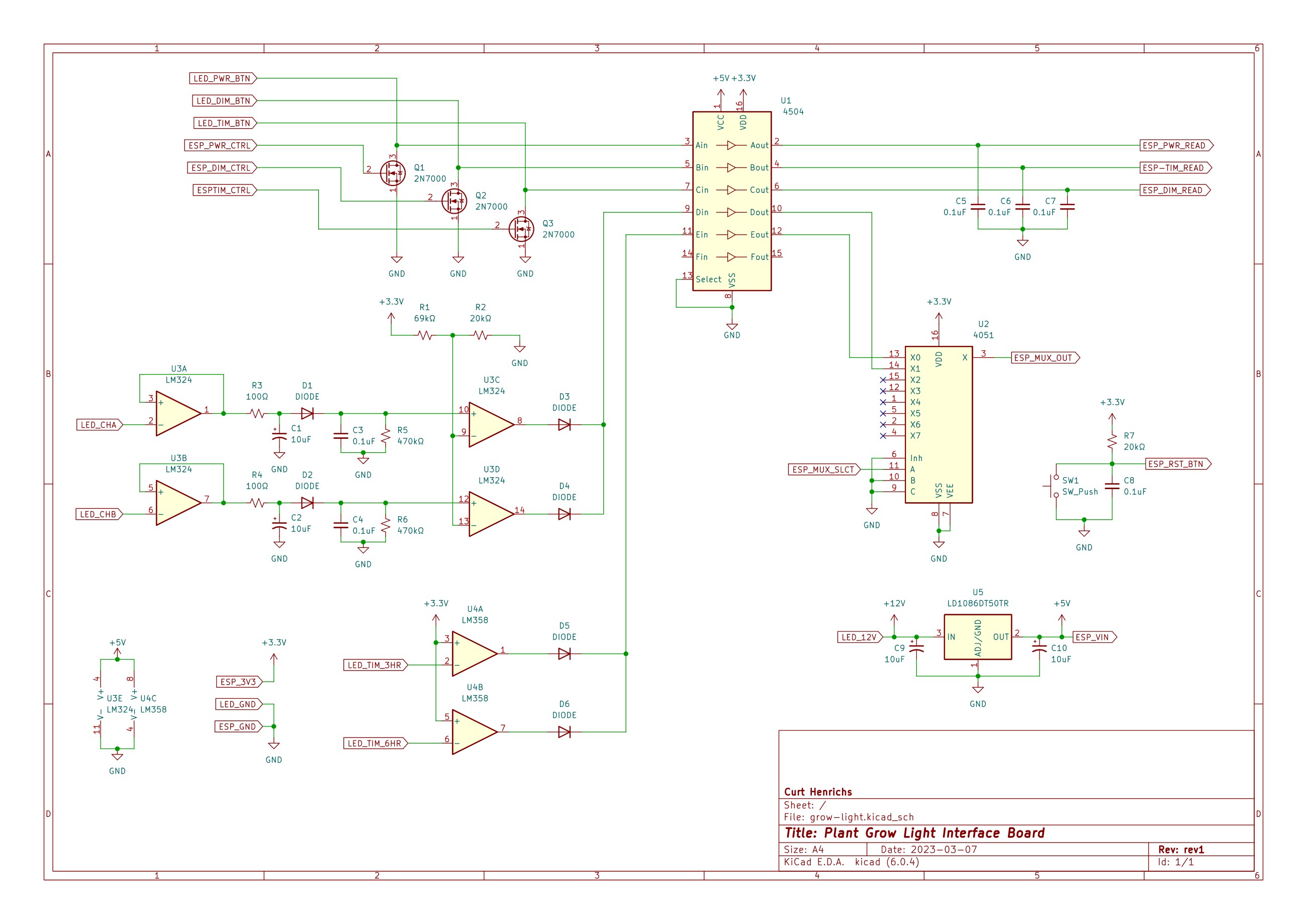
This time I drew the circuit in KiCad before building it (crazy right?). My design does four things:
- Three 2N7000 MOSFETs pull the button pads to ground on a 100 ms pulse from the ESP8266
- A CD4504 level shifter reads the same three pads back into the ESP8266 at 3.3V
- Each channel PWM line goes through an op-amp buffer, an RC filter, and a comparator, so a PWM wave reads as “on”. The two timer LED lines get the same treatment. The four results are diode-ORed down to two summary lines, “any LEDs on” and “timer not on manual”, and a CD4051 analog mux hands whichever one the firmware asks for to the ESP8266’s single analog pin
- An LD1086 5V regulator drops the grow light’s 12V for the NodeMCU, so the box runs off the grow light’s own wall wart
Plus a reset button for the Wi-Fi config, same as the air filter.
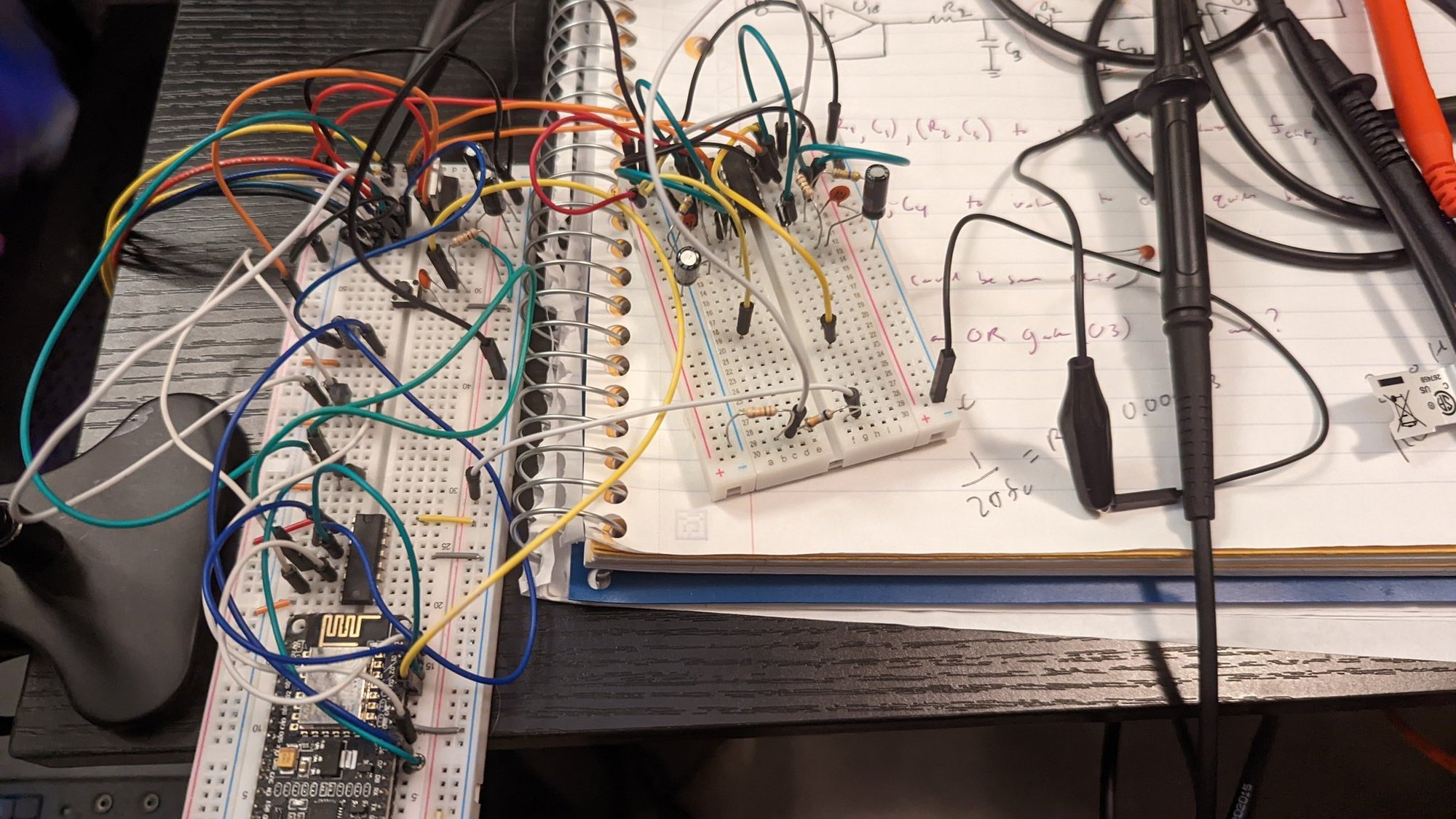
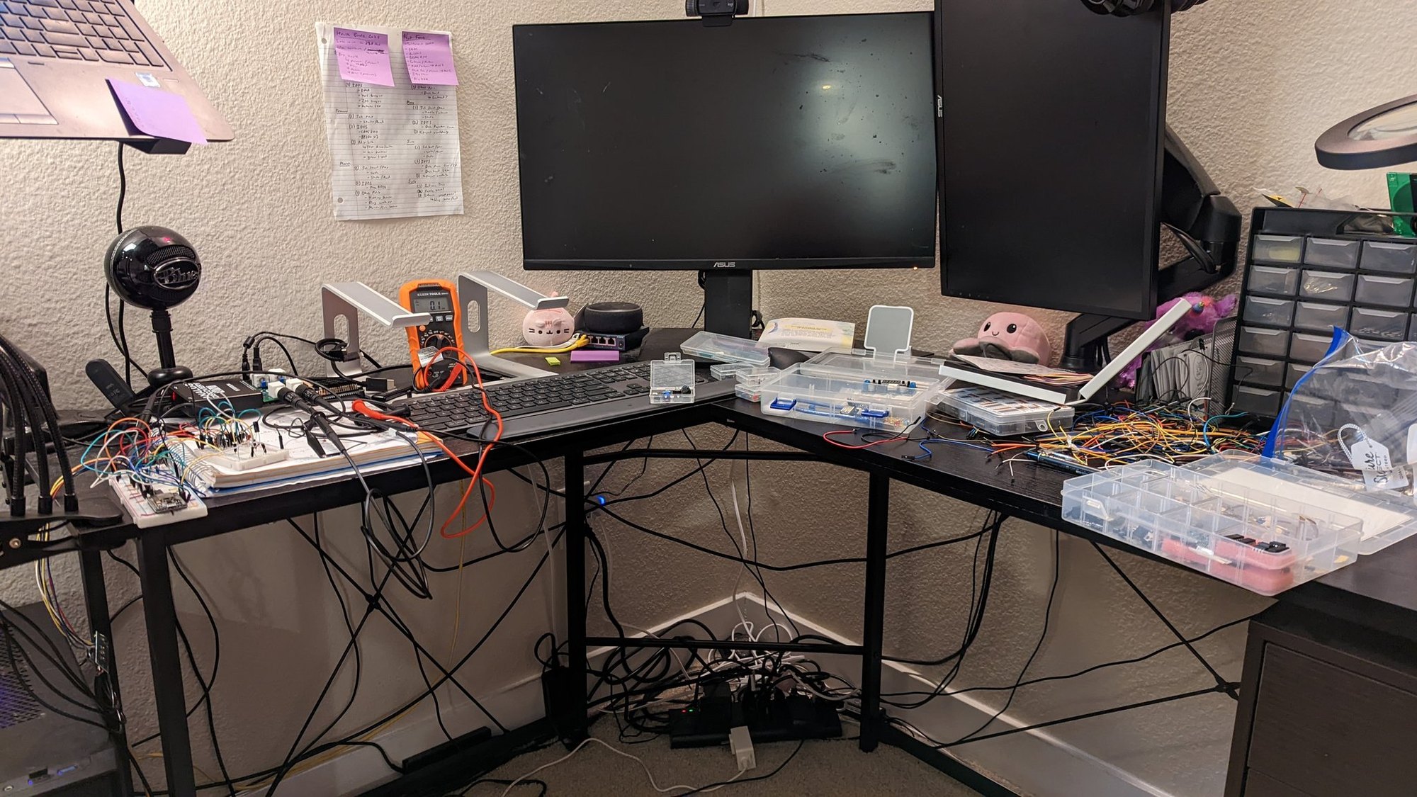
It all got breadboarded first, with the filter math worked out in a notebook next to it.
Assembly
With the breadboard version working, everything moves to perfboard.
-
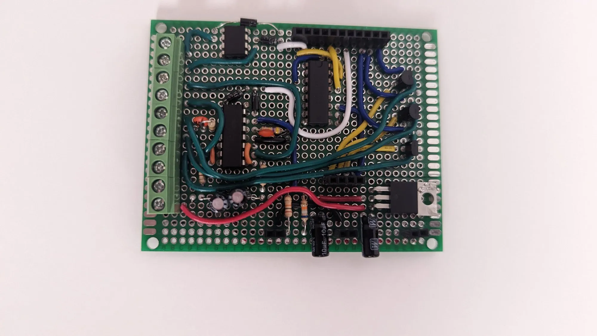
The base board. Screw terminals along the edge for the ten-wire harness to the stock controller.
-
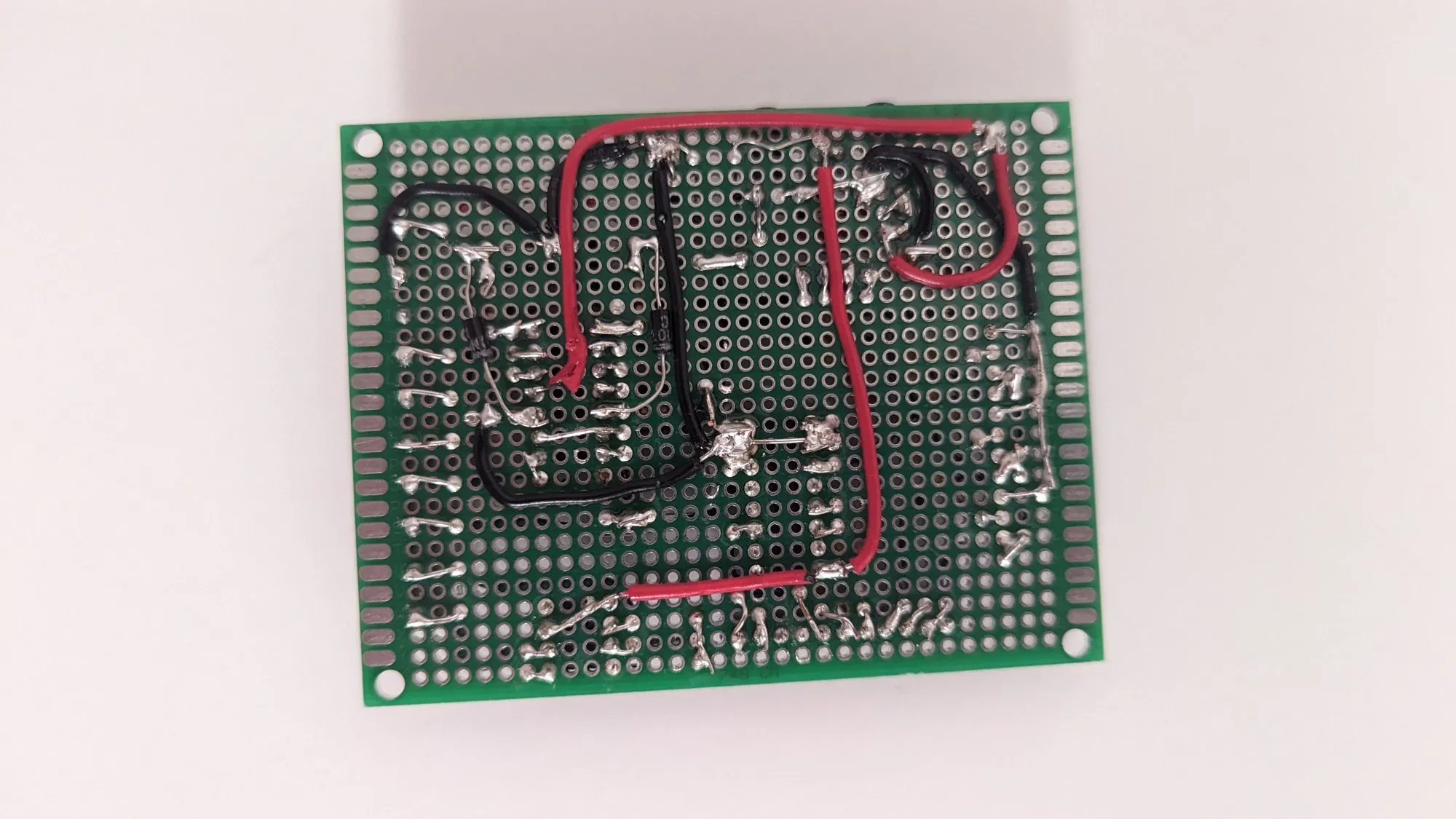
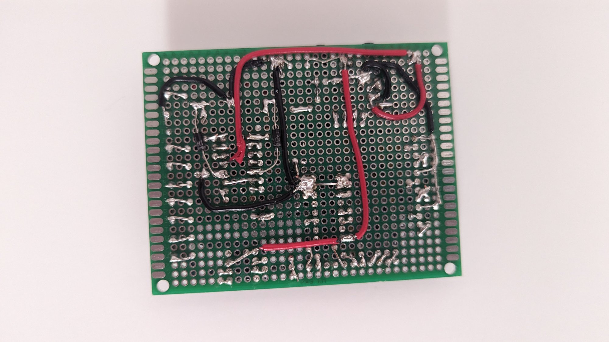
Underside. Power runs in red and black, the rest in bare wire along the pad rows.
-
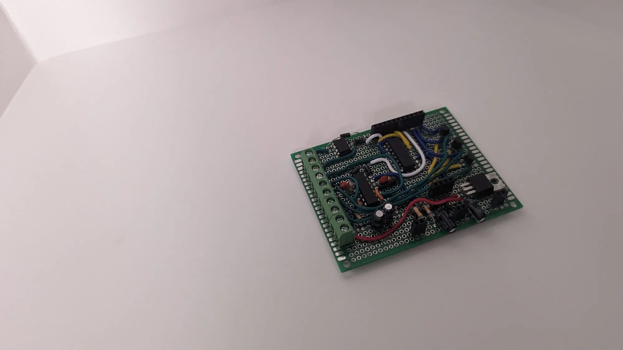
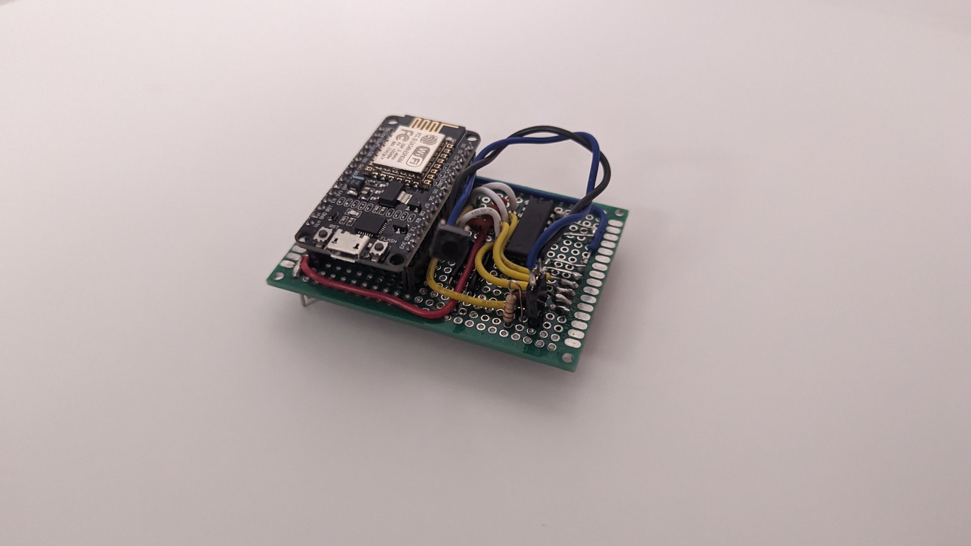
The NodeMCU sits on its own small perfboard to keep the ESP8266 daughterboard separate from the control adapter board. In theory I could swap in some other micro.
-
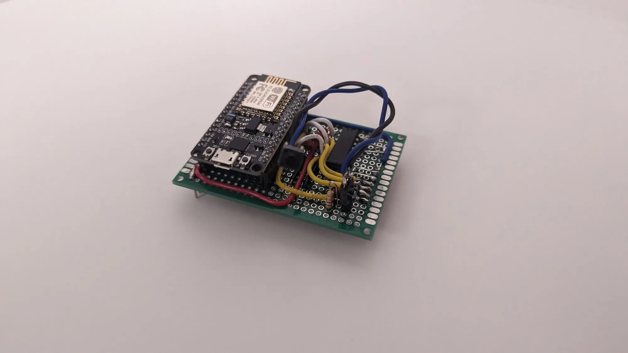
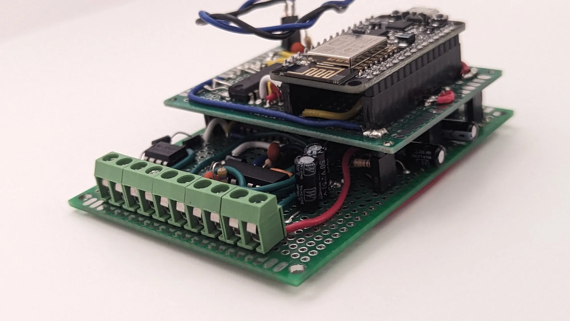
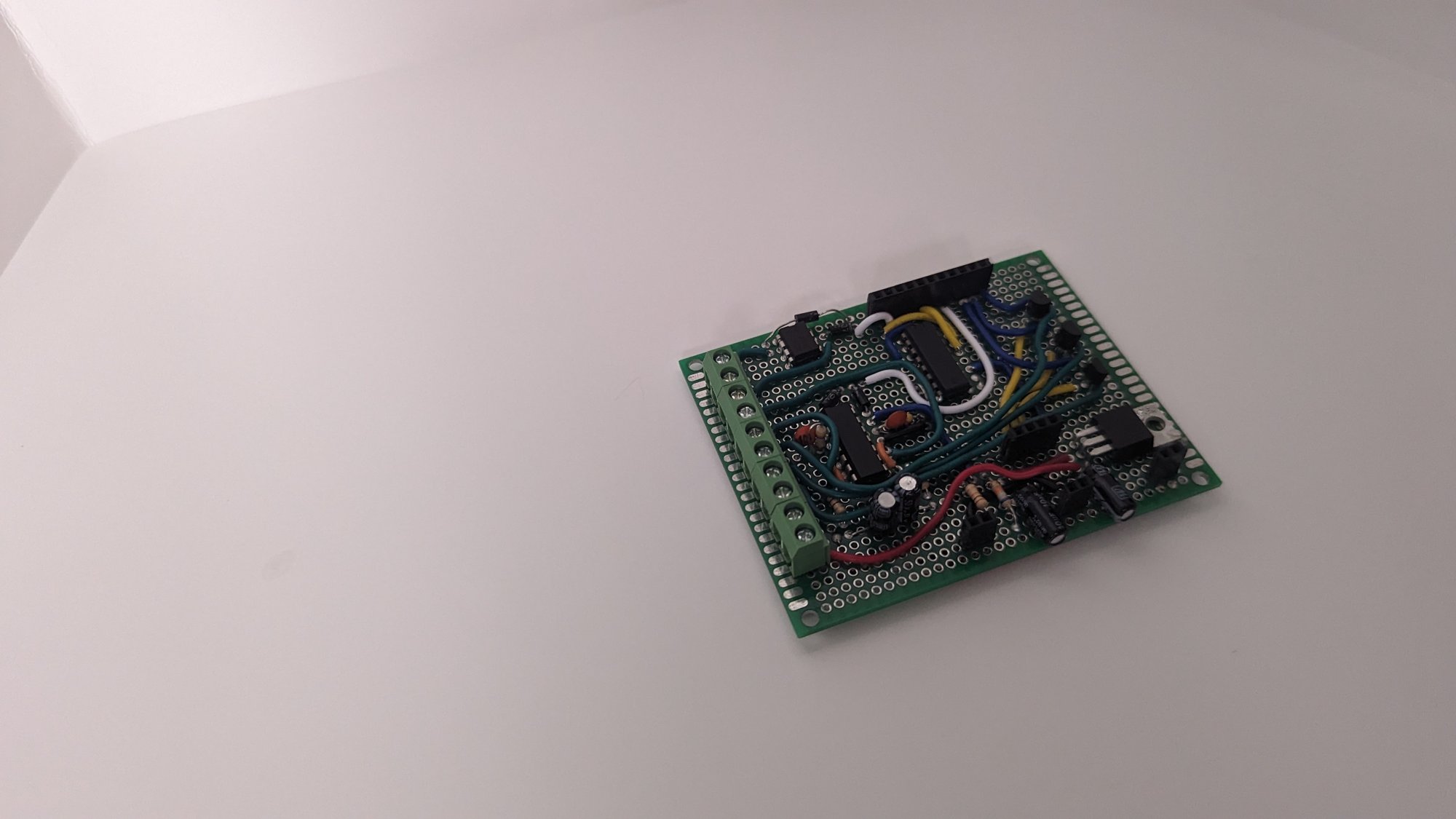
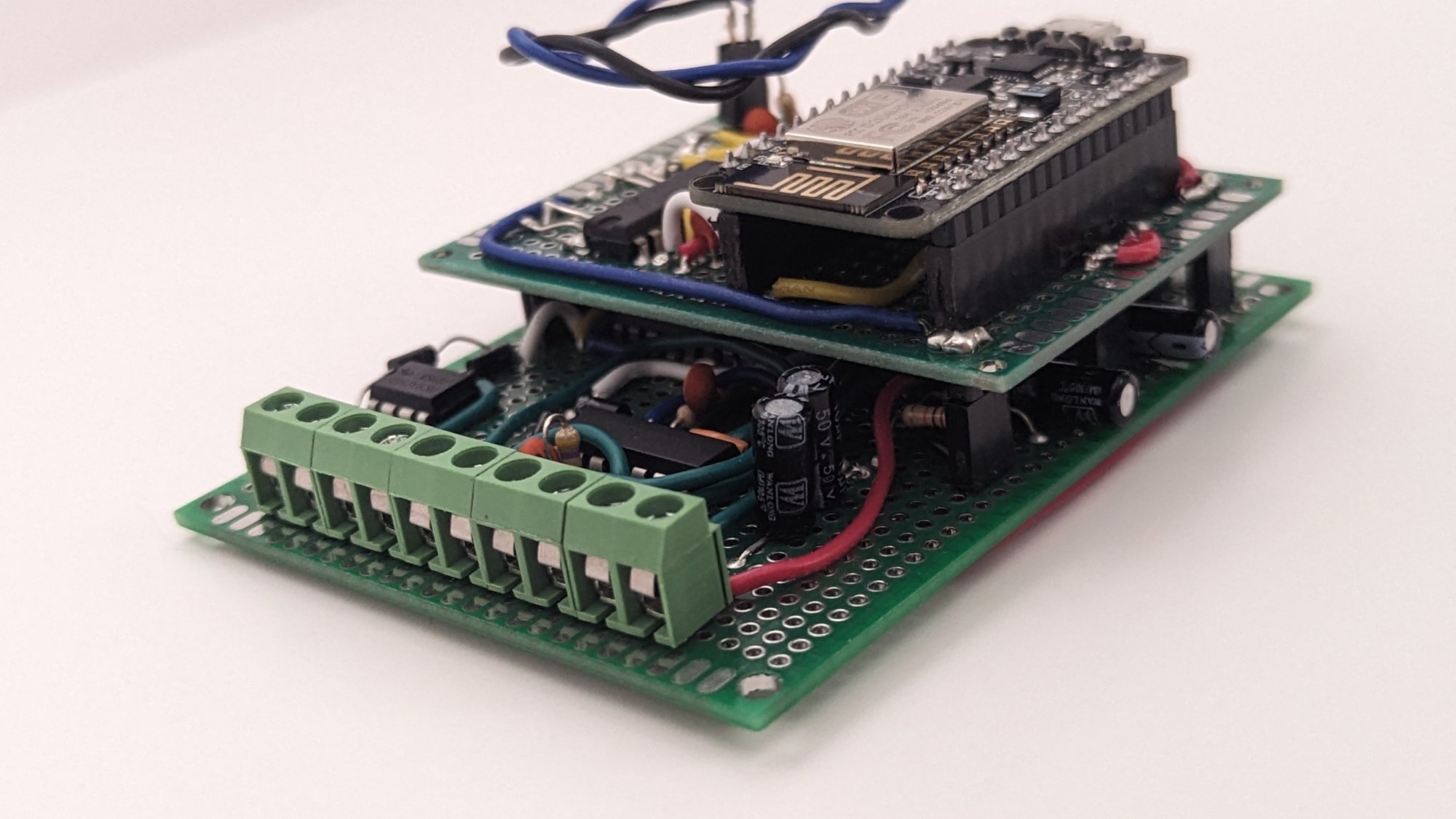
Stacked. The daughterboard plugs into headers on the base.
-
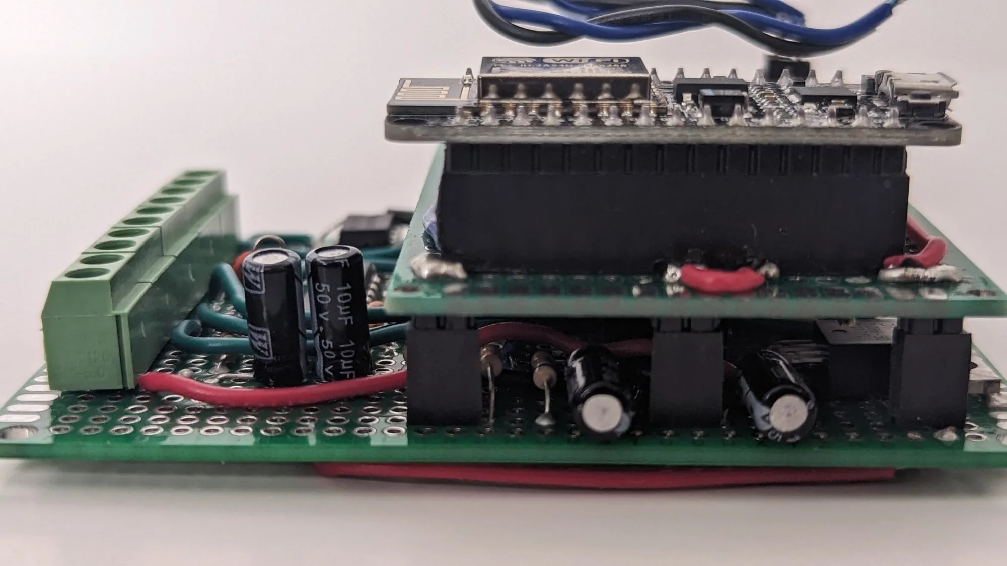
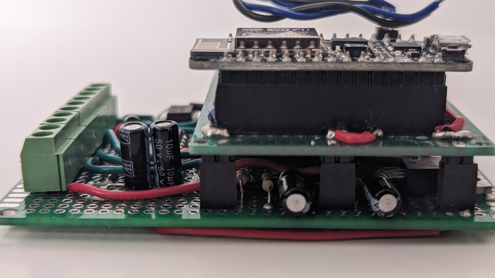
Side view. The daughterboard rides on tall header sockets, with the base board’s capacitors and resistors tucked underneath it.
-
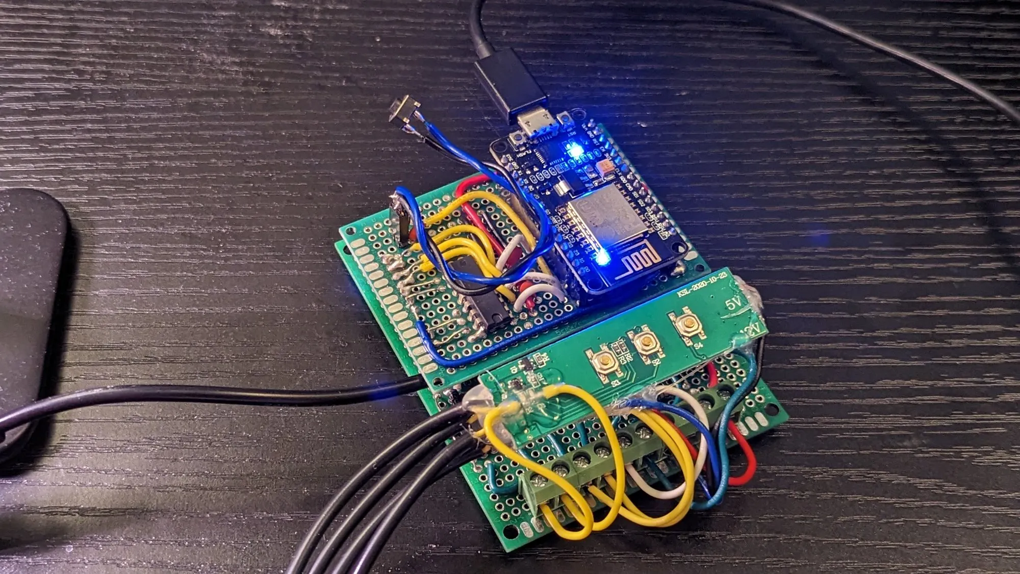
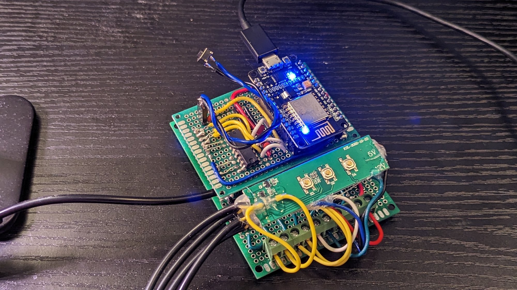
Wired in and powered on the desk. The blue LED means it is on Wi-Fi.
Enclosure
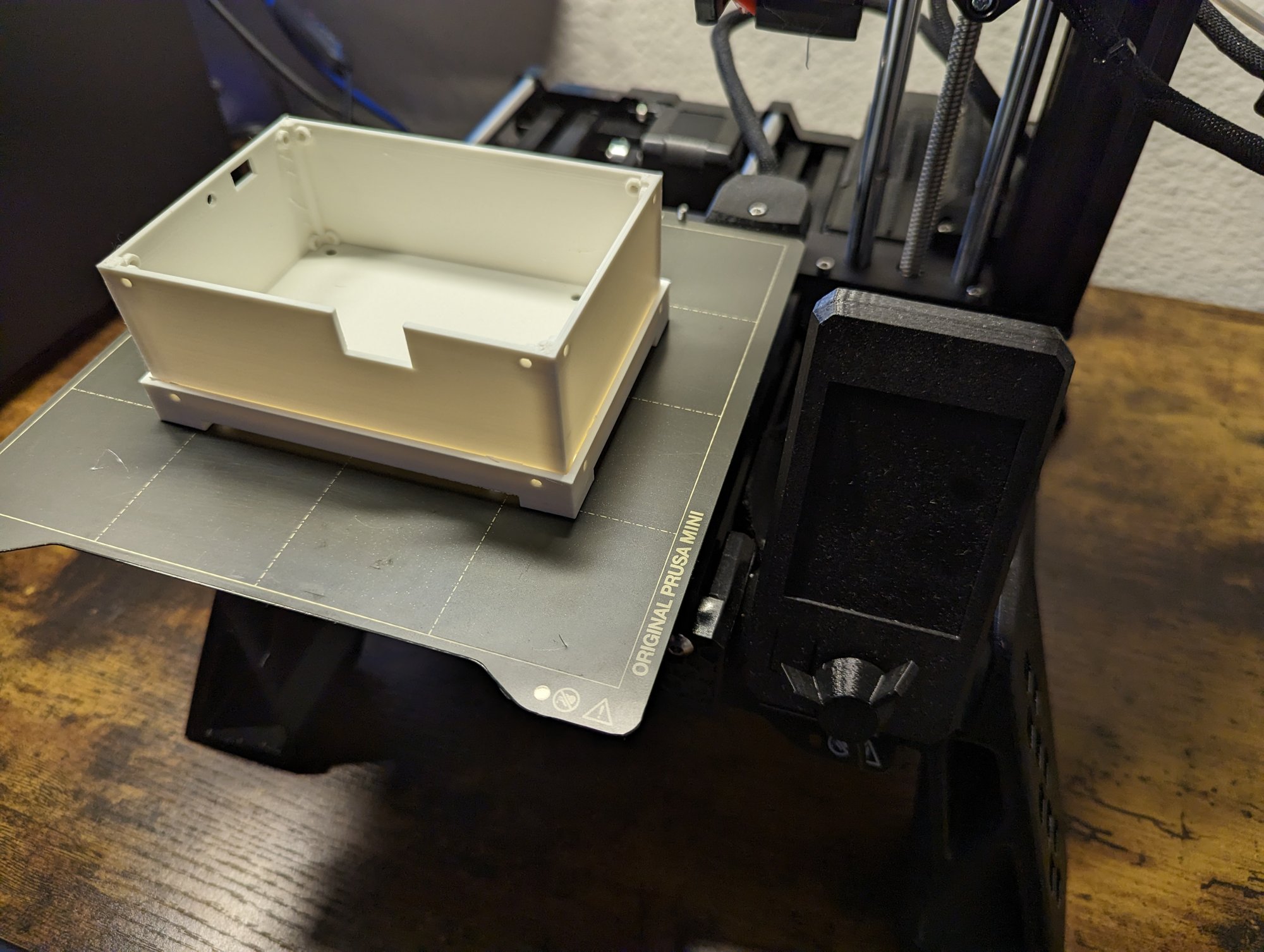
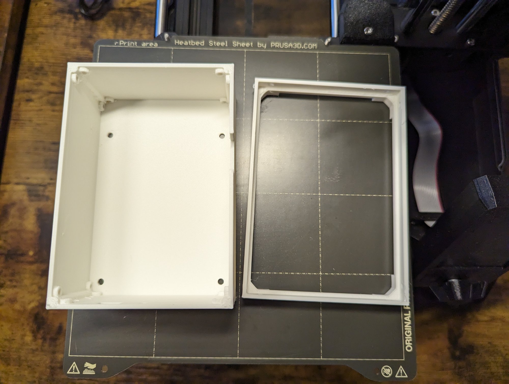
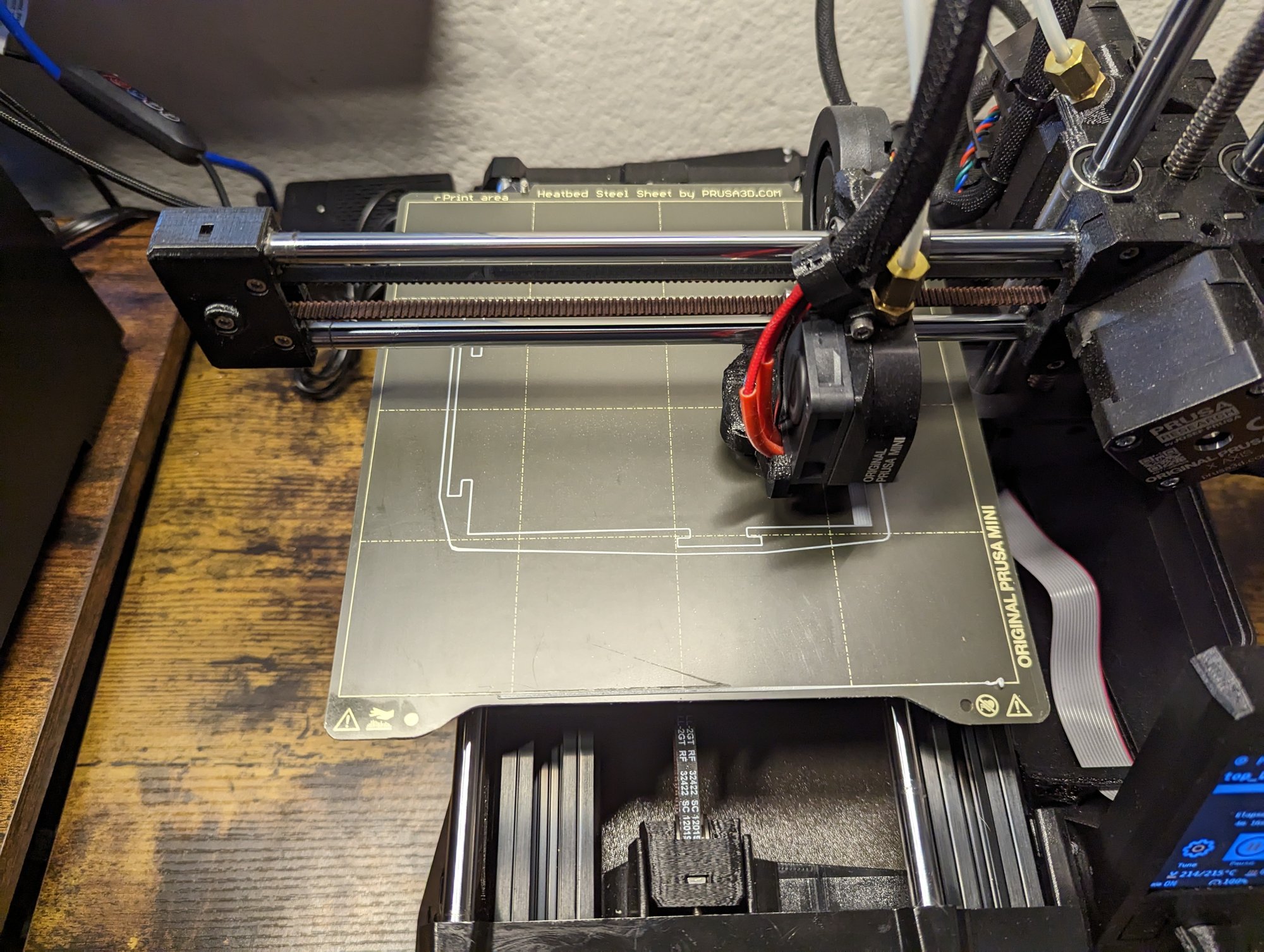
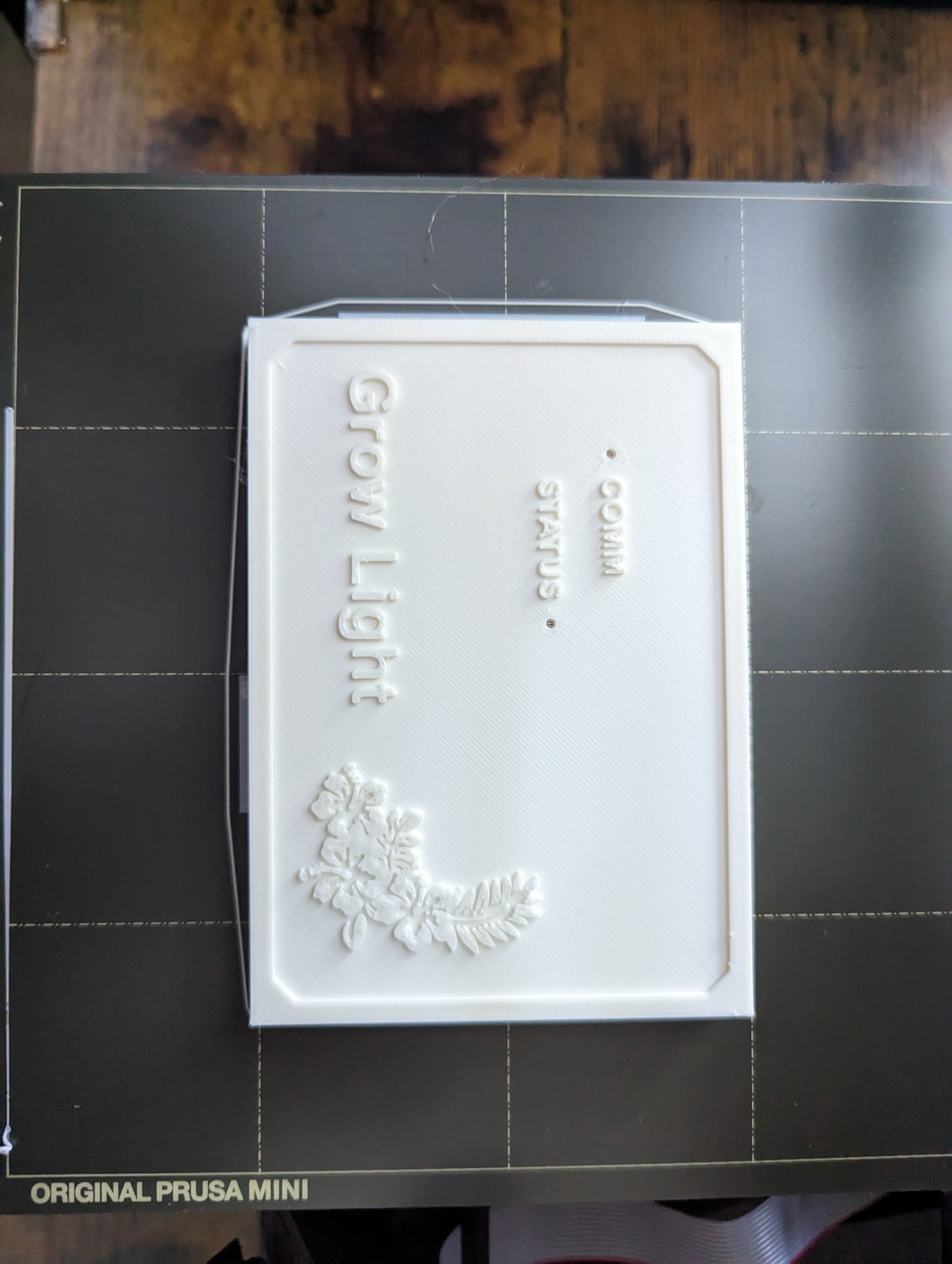
The bare stack needed a box (could you imagine me just nonchalantly watering my ESP8266). Good thing I have a Prusa Mini. I roughed out the dimensions on graph paper and modeled the box in Fusion 360, with cutouts for the reset button, the stock controller’s buttons, the cables, and the USB port for flashing, plus two pinholes for LEDs.
-
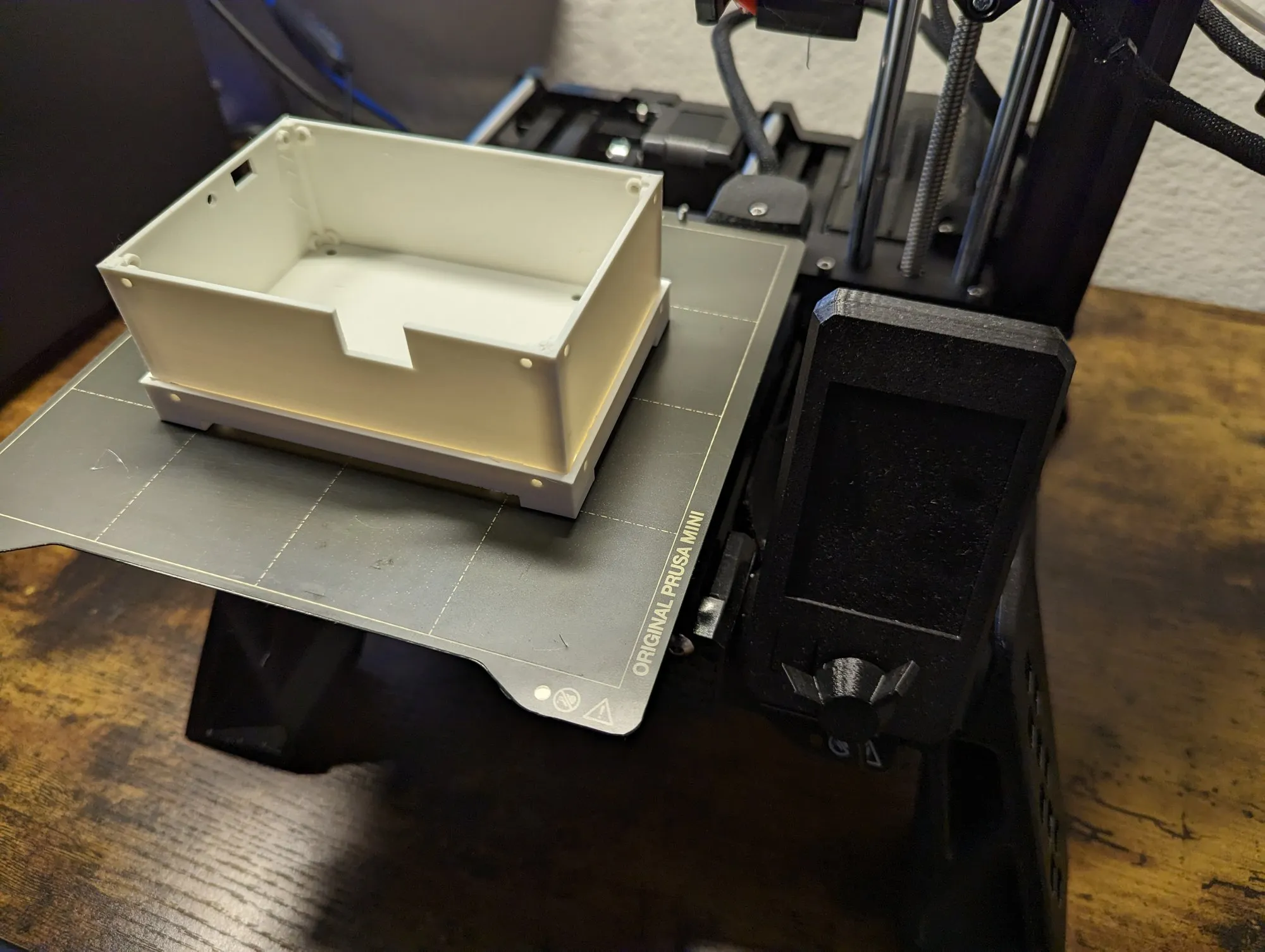
The box body off the printer. Openings in one wall for the cables.
-
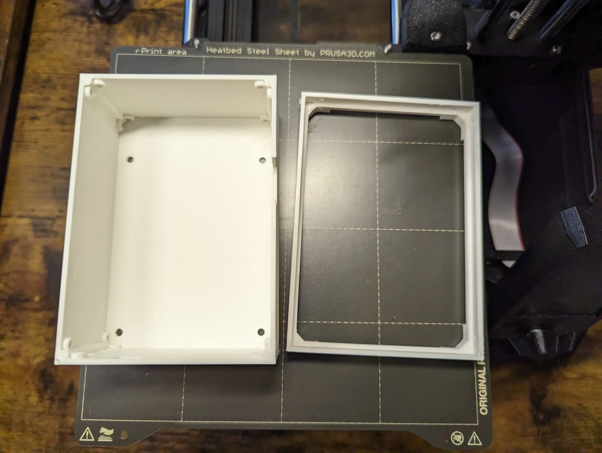
Box and lid.
-
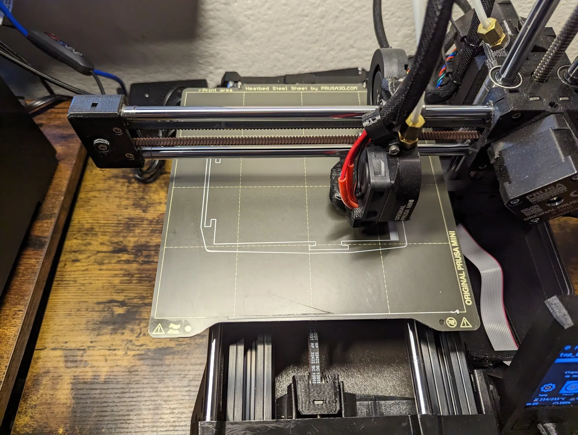
The lid printing. This one got a second pass with the lettering.
-
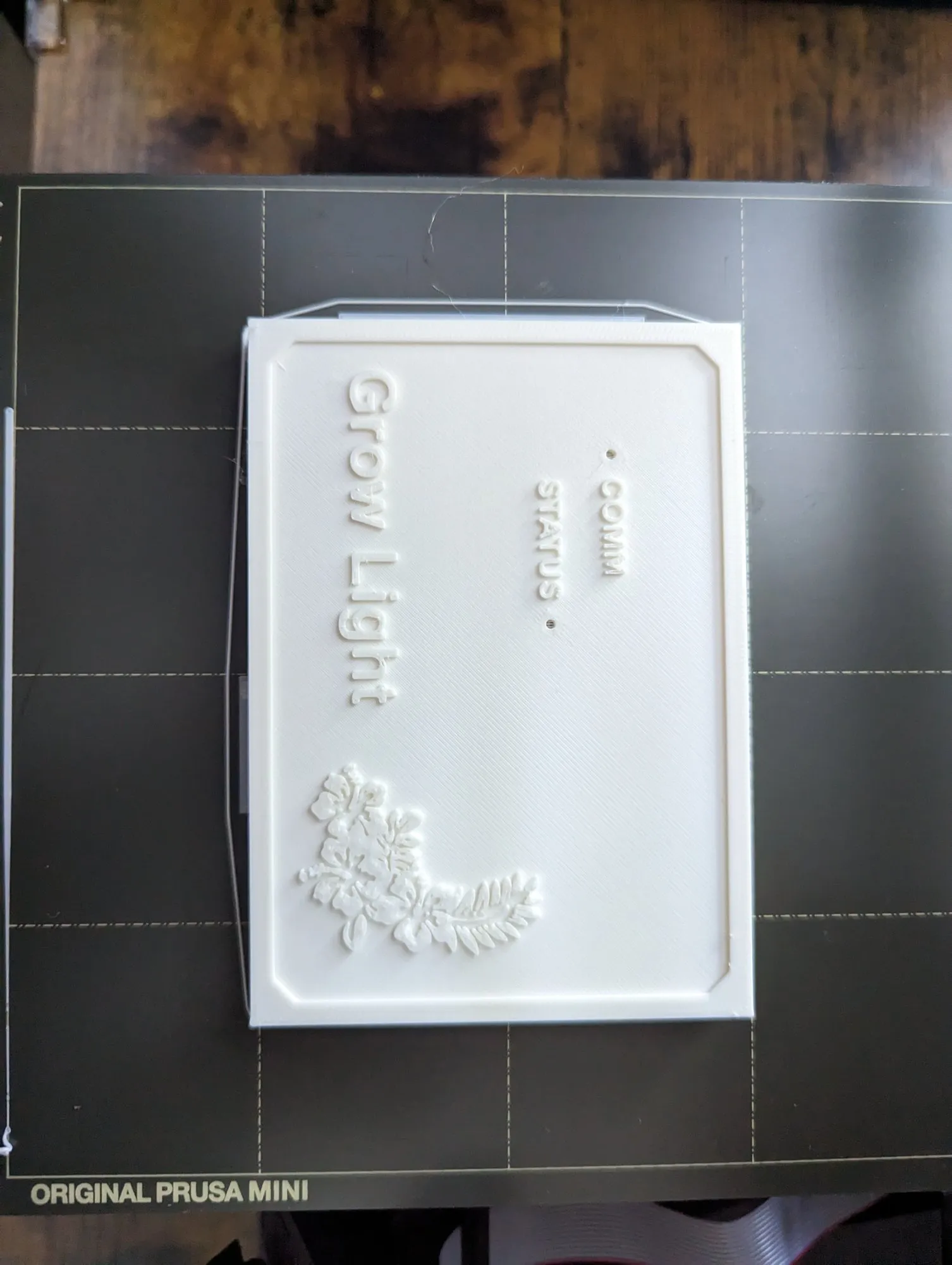
Lettering on the lid, plus the two pinholes labeled COMM and STATUS.
-
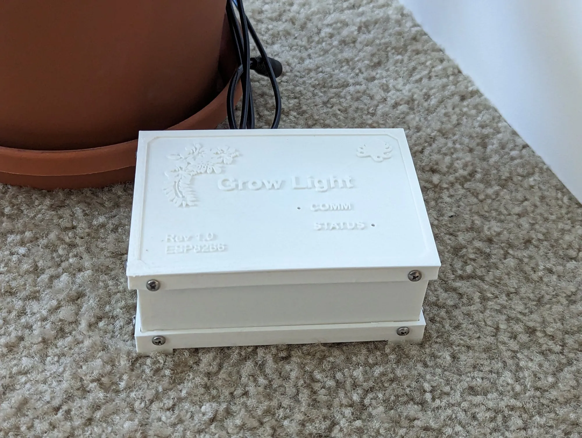
Closed up and sitting next to the plant.
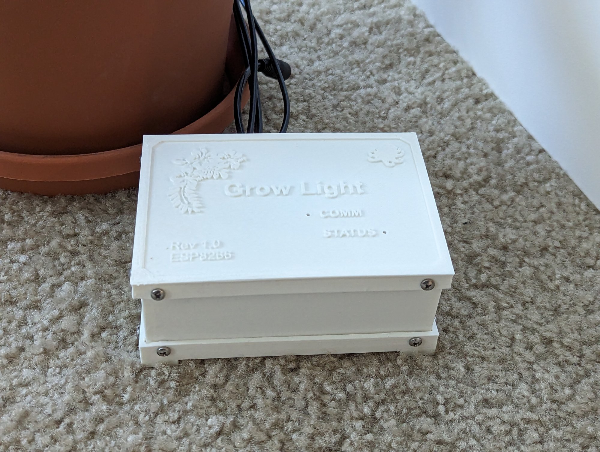
The STLs for the box, lid, feet, and spacers are in the firmware repo under Enclosure, next to the KiCad files.
The finished grow light.
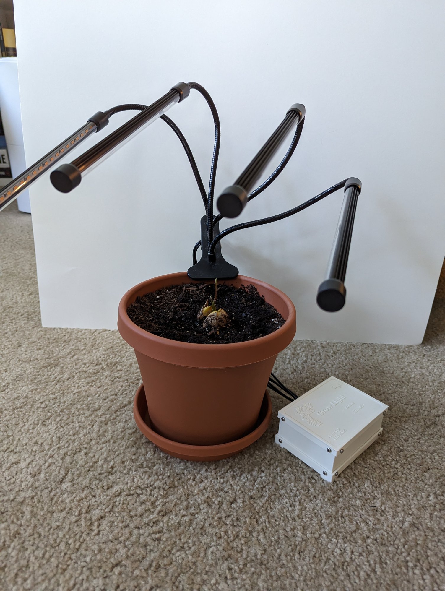
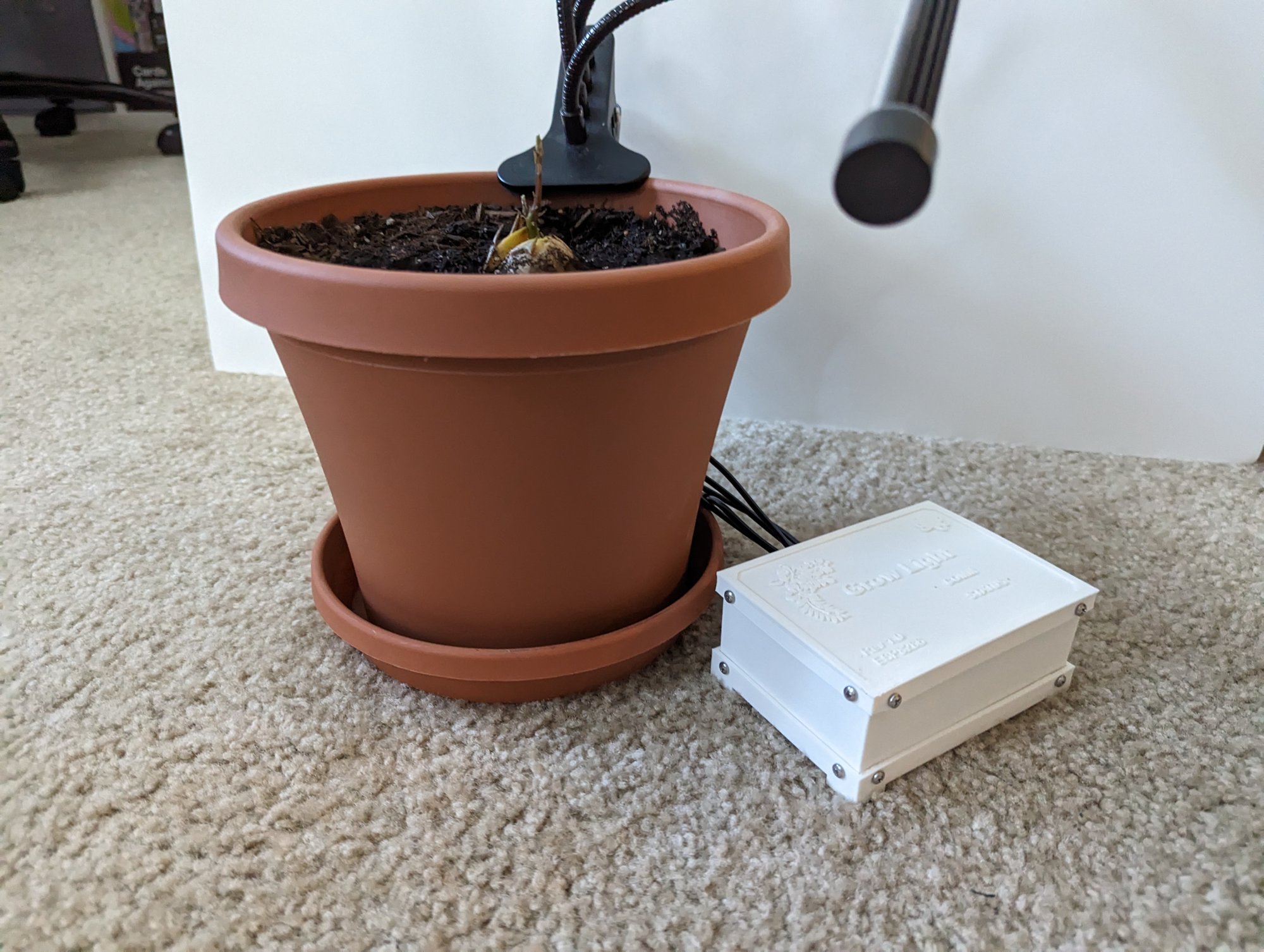
Firmware
The firmware lives in the ESP8266_Plant_Grow_Light repo on GitHub.
The grow light skipped the fauxmoESP stage that the air filter took. All I wrote in 2022 was a test sketch that printed the three button pins to serial. The real firmware came after the air filter’s V1 and was built on the Okos Polip client library from the start.
Okos Polip has its own post now. The short version is that the device polls a server for the state it should be in, pushes its state when something changes, and takes remote procedure calls for anything that is not plain state.Pin Map
| Pin | Direction | Purpose |
|---|---|---|
D0 | out | Click the power button |
D7 | out | Click the dimming button |
D6 | out | Click the timing button |
D5 | in | Read the power button pad |
D1 | in | Read the dimming button pad |
D2 | in | Read the timing button pad |
D8 | out | Mux select. Low reads “any LEDs on”, high reads “timer not manual” |
A0 | in | The mux output |
D3 | in | Reset button for the Wi-Fi config |
LED_BUILTIN | out | Status blink |
Hardware Control
The controller has three cyclic states, so the firmware keeps a current state and a target state for each.
typedef enum _led_channel { LED_OFF, LED_ALL, LED_CHA, LED_CHB } led_channel_t;
typedef enum _led_dimmer { LED_DIM_0, LED_DIM_1, LED_DIM_2, LED_DIM_3, LED_DIM_4 } led_dimmer_t;
typedef enum _led_timer { LED_TIMER_OFF, LED_TIMER_3HR, LED_TIMER_6HR, LED_TIMER_12HR } led_timer_t;

typedef struct _led_state {
    led_channel_t ch;
    led_dimmer_t dim;
    led_timer_t tim;
} led_state_t;
Getting from current to target is the same pulse-and-cooldown loop as the air filter, one button at a time. Power first, because turning the grow light off resets the dimmer and timer on the stock controller, then timer, then dimmer.
if ((currentTime - _cooldownTime) > COOLDOWN_THRESHOLD) {
    _cooldownTime = currentTime;
    if (_currentState.ch != _targetState.ch) {
        powerStateTransition(_currentState);
        pulsePowerBtn();
    } else if (_currentState.tim != _targetState.tim && _currentState.ch != LED_OFF) {
        timerStateTransition(_currentState);
        pulseTimerBtn();
    } else if (_currentState.dim != _targetState.dim && _currentState.ch != LED_OFF) {
        dimmerStateTransition(_currentState);
        pulseDimmerBtn();
    }
}
The catch with a cyclic controller is that the ESP8266 has no idea where in the cycle it is at boot. That is what the summary lines are for. On startup the firmware jogs the power button until “any LEDs on” reads false, then jogs the timing button until “timer not manual” reads false. Now it knows the controller is at Off, full brightness, no timer, and it can count from there.
static void _homeLEDController(void) {
    while (readStateSummary_ledsOn()) {
        pulsePowerBtn();
        delay(COOLDOWN_THRESHOLD);
    }
    while (readStateSummary_timerOn()) {
        pulseTimerBtn();
        delay(COOLDOWN_THRESHOLD);
    }
    _currentState.ch = LED_OFF;
    _currentState.dim = LED_DIM_4;
    _currentState.tim = LED_TIMER_OFF;
}
The hardware timer never gets used after that. The firmware forces it off and runs its own timer against NTP time instead, since a duration the server can see is more useful than a state I can only read off two LEDs.
The air filter pushes state when someone presses its button. The grow light does not. I tried it, with the read pins on interrupts, and the firmware kept reacting to its own clicks. So the interrupts came out, and the read pins only serve homing and manual fix-ups.
Okos Polip State
The device’s serial is grow-light-0-0000. State is power, intensity, channels, and an optional timer.
static void _pushStateSetup(polip_device_t* dev, JsonDocument& doc) {
    JsonObject stateObj = doc.createNestedObject("state");
    stateObj["power"] = (_targetState.ch == LED_OFF) ? "off" : "on";
    stateObj["intensity"] = _targetState.dim;
    if (_targetState.ch == LED_OFF || _targetState.ch == LED_ALL) {
        stateObj["channels"] = "all";
    } else if (_targetState.ch == LED_CHA) {
        stateObj["channels"] = "a";
    } else if (_targetState.ch == LED_CHB) {
        stateObj["channels"] = "b";
    }
    if (_softTimerActive) {
        JsonObject timer = stateObj.createNestedObject("timer");
        timer["timestamp"] = _softTimer.timestamp;
        timer["duration"] = _softTimer.hours;
    } else {
        stateObj["timer"] = nullptr;
    }
}
Polling is the reverse. Power, channels, and intensity come down from the server and become the target state. The timer is deliberately ignored on a poll. Timers are set through an RPC instead.
This device also has RPCs, which the air filter did not. timer takes a duration in hours. When it expires the grow light turns off and the RPC reports success. home re-runs the boot homing routine, with an option to keep the state the jog lands on. Both can be cancelled from the server. The client library tracks pending, acknowledged, and succeeded, and pushes a notification at the end.
One gotcha for anyone using the library. The default JSON document size was too small once RPCs were in the response. This firmware doubles it. It took me a while to notice, which tells you how often the grow light needed attention.
Conclusion
In practice I ended up jogging the grow light straight from the MongoDB database, and Okos Polip itself has since been abandoned. Per usual, about half done.
The avocado tree, meanwhile, grew up. It no longer needs the grow light at all.
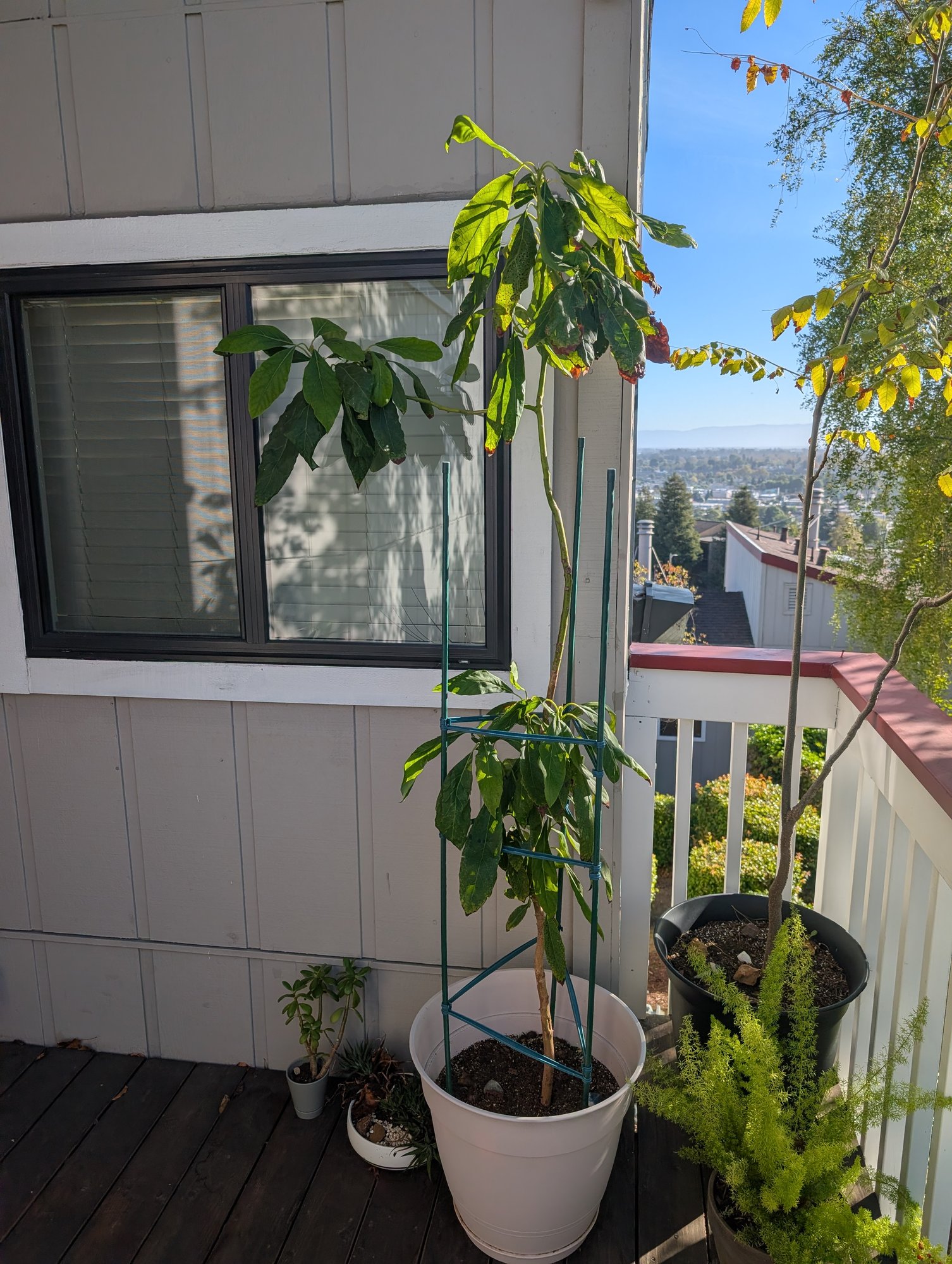
It took some sun scorch this summer. As of writing it’s late September, and it’s probably looking forward to winter to rest.